Notice. New forum software under development. It's going to miss a few functions and look a bit ugly for a while, but I'm working on it full time now as the old forum was too unstable. Couple days, all good. If you notice any issues, please contact me.
disco4now Guru Joined: 18/12/2014 Location: AustraliaPosts: 1109
Posted: 10:41am 09 Nov 2018
Copy link to clipboard
Print this post
There have been a number of occasions where people have build various Micromites, E100 etc and get to the point where they can talk to the console, but have has issues with LCD etc. It a long time since I have used a BiPolar test lamp but when I was using it back in the day, it was the only thing you used other than a circuit.(PMG,Telecom)
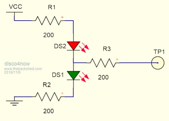
I built this LED version using a red and green LED and three 200ohm resistors.
You connect to 3.3v and Gnd and when the probe touches a high logic the green Led lights and when touches a low logic level the red lights, and neither lights for a high impedance. With the resistors touching 5v is OK as well.
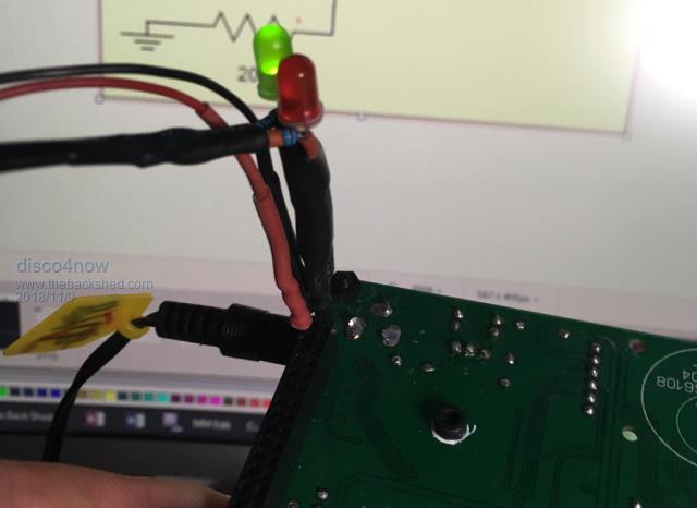
Here it is probing the LCD connector on an E100
So if you have the console working you can load the program below and use it to set the pins of interest high and low and check them for continuity and shorts using the test lamp.
The program contains a list of the connections you are interested in testing and their corresponding MCU pins. The Space Bar steps through the defined tests and the console tells you which connection to probe.
A good test will be green Led 1 second,No Leds 1 second, Red Led 1 second, No leds 1 second during the four step test. The Leds swapping from Green directly to Red with no off time indicates a short, you are on the wrong pin or there is an external pullup etc.
1. The pin is set high and all other pins set low. The pin being tested should show as high. 2. The pin is set OFF and all other pins remain low. The pin being tested is not high or low and both test LEDs are off. If either led lights there is possibly a short to another pin . 3. The pin is set low and all other pins set high. The pin being tested should show as low. 4. The pin is set OFF and all other pins remain high. The pin being tested is not high or low and both test LEDs are off. If either led lights there is possibly a short to another pin .
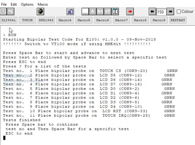
A pin with a pullup resistor will show high for steps 2 and 4 Initially set to test D0-D7 LCD-RST T-CS and T-IRQ on and E100 Board
The console as show during a full set of tests
The data could be adjusted to test more connections on the E100 or for any other board. Once you get the console working you can use it to test/troubleshoot board issues.
Chopperp Guru Joined: 03/01/2018 Location: AustraliaPosts: 1123
Posted: 07:36am 10 Nov 2018
Copy link to clipboard
Print this post
Hi Gerry,
Looks interesting.
Been meaning to let you know that your MMreplace.exe prog is still working well with MMEdit and my CMM. Certainly makes dealing with Library files so much easier (as long as I remember to set the directives properly).
Thanks again
BrianChopperP
Grogster Admin Group Joined: 31/12/2012 Location: New ZealandPosts: 9933
Posted: 09:11am 10 Nov 2018
Copy link to clipboard
Print this post
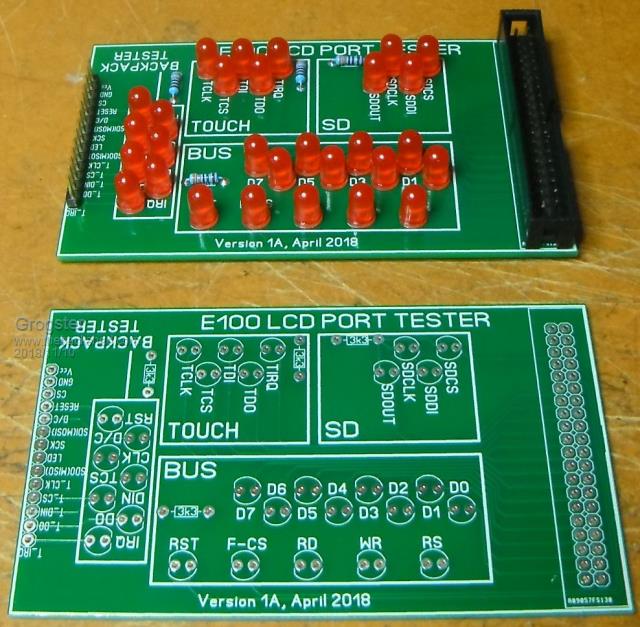
I also have a tester PCB available, for those who are curious if their port pins are working correctly. Third from the bottom of the page. Tests both the parallel and the SPI based MM boards.
MMBASIC code to use the tester is available from my downloads page. PCB only. You need to supply the components.
Smoke makes things work. When the smoke gets out, it stops!