
|
|
Forum Index : Microcontroller and PC projects : 2A Buck-Boost PSU with LCD for $5...
| Author | Message | ||||
Grogster Admin Group Joined: 31/12/2012 Location: New ZealandPosts: 9934 |
These seem to work quite well. Link to $5 PSU module with LCD They say it is capable of up to 3A, but I probably would not push it past 2A with the little heatsink it has on it. It is a nice little unit, with fully adjustable output voltage and current. Vout can be 0.5v to 30v, and Vin can be 5.5v-30v. I used 12v for my tests. It comes it a little static-proof bag, with a stick-on heatsink and four little plastic stand-off's, but they are non-adhesive, so I won't use those.(I have plenty of stick-on PCB stand-off's) 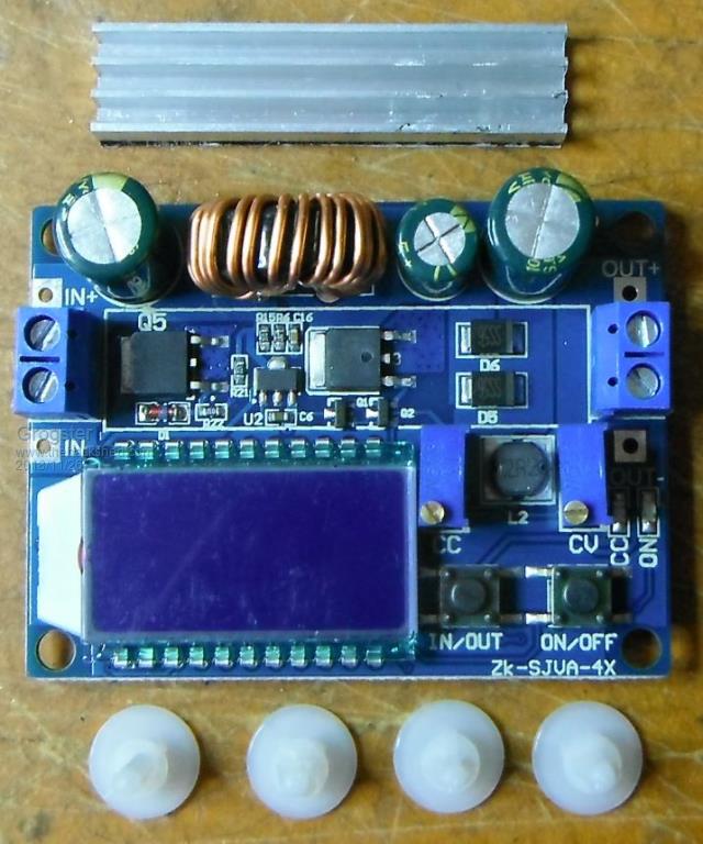 A couple of these with a 12v input, and you have a nice CHEAP dual-rail, adjustable, current-limited bench PSU. The photos of it on the listing are far better then the ones I tried to take, so you can see all you need from there. Voltage adjustment is smooth. Current adjustment is very jerky in terms of it changing all the time on the LCD as you set it. You have to average that out in your head a bit, but it works well enough as a general purpose current limit indication. The ON/OFF button is useful - you can easily turn the output off to fit a short-circuit on the output to then set the current limit, then press the button to turn the output back on again and adjust the current limit, press the button to turn off the output, remove the short and connect your load, press the button..... Note that doing that on a PSU without any current limit could probably send that PSU to the big silicon heaven in the sky. The IN/OUT button allows you to show either the input voltage to the module, or the set output voltage. What I like about a module such as this one, is that buck/boost so one input voltage can run the thing, but you can get output voltages bigger then the input voltage out of them, making them most suitable for....just about anything, really, and you don't need to worry about the input voltage being larger then the output voltage thing. I seem to recall that some of these buck/boost modules don't really like you setting the output voltage the same as the input, as then they try to switch between buck and boost mode and this can cause issues. I would have to test that idea on this one. I have not had a chance to measure the output ripple on these things, but might still do that if anyone is interested. They use a 180kHz switching frequency, and the output has a 105 degrees Sanyo 470uF 35v cap.(so does the input) If there was excessive ripple, that is usually reasonably easy to settle down by adding a simple LC filter to the output. Perhaps I'll have to warm up the spectrum analyser and see!  But for the price, they seem to work OK with initial tests, and they would make a nice cheap bench supply for anyone needing one, but not wanting to spend any more then they have to. Smoke makes things work. When the smoke gets out, it stops! |
||||
| Pete Locke Senior Member Joined: 26/06/2013 Location: New ZealandPosts: 182 |
Thanks for the link Grogster. CV & CC, ideal for charging second hand LiPo cell phone batteries I use for model plane flying. And at that price it's not even worth opening up the immensely powerful Windows Paint to draw out a circuit :-) Looks like they've just sold another one  Cheers Pete'. |
||||
Chopperp Guru Joined: 03/01/2018 Location: AustraliaPosts: 1123 |
Great units. Just be aware that with most of these supplies with current limiting, you can't tie the input & output negative connections together if you want the limiting to work. The current shunt is normally connected between the two. I.E. The input has to be fully isolated from the output for the current limiting to work. Been caught out with this with using a boost unit where there was a common ground for both the I/P & the O/P. Had to do without the current limiting. ChopperP |
||||
| Bill7300 Senior Member Joined: 05/08/2014 Location: AustraliaPosts: 159 |
Good find Grogs. One might be just the thing I need at the moment, away from home base, to get the residual charge in one of my 18V LiOn drill batteries back above the point where the supplied charger refuses to charge it. Bill Bill |
||||
| Grogster Admin Group Joined: 31/12/2012 Location: New ZealandPosts: 9934 |
@ ChopperP - Yes, you are indeed correct.  The output has a couple of current sense resistors in series with it. This is not a deal-breaker, you just have to make sure that your input voltage ground is isolated from the output ground - just as you say. This is easy so long as you know you have to do it! The output has a couple of current sense resistors in series with it. This is not a deal-breaker, you just have to make sure that your input voltage ground is isolated from the output ground - just as you say. This is easy so long as you know you have to do it!  Smoke makes things work. When the smoke gets out, it stops! |
||||
| The Back Shed's forum code is written, and hosted, in Australia. | © JAQ Software 2026 |
