
|
|
Forum Index : Microcontroller and PC projects : Armmite L4 PCB design for comment
| Page 1 of 2 |
|||||
| Author | Message | ||||
| matherp Guru Joined: 11/12/2012 Location: United KingdomPosts: 11166 |
I've designed a PCB for the Armmite L4 and am interested in comments. The philosophy behind the design is that the Armmite L4 is targetted at low power battery applications which may be remote and where data-logging may be required. The chip chosen is the 48-pin STM32L431CCT6 or STM32L433CCT6. The design uses the Raspberry Pi 3 footprint so will be compatible with Raspberry Pi cases and HATs/pHATs. It has the standard Pi 40-pin header and all "special function" Pi pins are replicated using the Armmite, i.e. UART, SPI, I2C PWM In addition there is a separate SPI display header which will will take ILI9341, ST7735 (some versions - check pinout), ILI9163 and Nokia 5110 (some versions - check pinout) and two I2C headers with differing pinouts which between them will take all versions of SSD1306 OLED displays - note TOUCH on the ILI9341 is not supported in the Armmite L4 firmware. The display backlight can be controlled using PWM2A. The PCB has a jumper for LOAD and RUN. In the LOAD position you can program the Armmite L4 firmware over the console connection. In the run position the Armmite firmware runs as normal - note no special programmer is needed to upload the Armmite firmware. There is a battery backup for the RTC There is a header for an IR receiver There is a jack socket for the DAC outputs There is a pad for a Winbond SPI flash allowing the Armmite's full file system to be used. There is a header for an HS12 radio module Most importantly, there is a location for a MINI USB 1A Lithium Battery Charging Board Charger Module With Protection TP4056 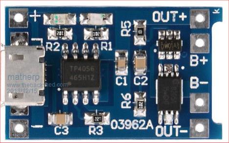 This allows the PCB to be battery operated and provides both a charging capability and low battery protection. The charging is through the micro-USB connector on the main PCB and there is a shorting link to allow the PCB to be used without the battery module attached. Schematic is attached together with layout pictures which have the ground fill removed for clarity. Comments appreciated. 2018-12-15_212159_HAT64_-_Project.pdf 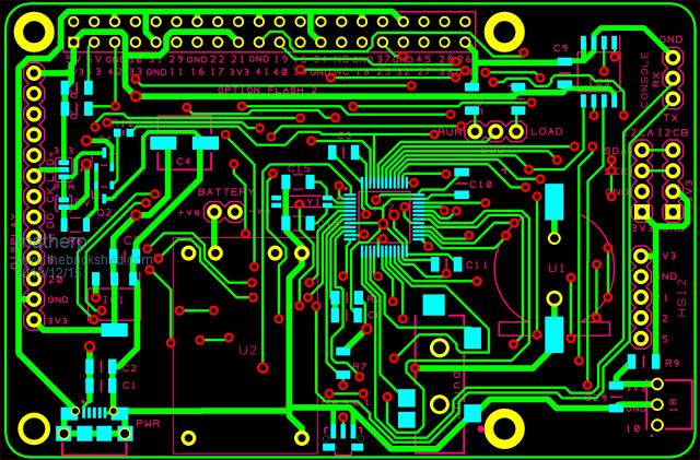 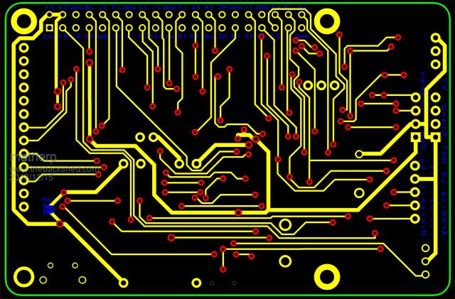 |
||||
| sagt3k Guru Joined: 01/02/2015 Location: ItalyPosts: 313 |
Hi matherp An excellent solution, do you wakeup on A0 or B1, for resume from Raspberry gpio? Antonio |
||||
| matherp Guru Joined: 11/12/2012 Location: United KingdomPosts: 11166 |
Sleep specifically enables A0 but if either B0 or A12 are set up as CIN or FIN then they will also wake up from sleep |
||||
| lizby Guru Joined: 17/05/2016 Location: United StatesPosts: 3733 |
Great solution with lots of bases covered. I very much appreciate the Raspberry Pi pin header footprint--also the lithium battery charging option. (Hope someone will do populated boards.) For a remote, low-powered system, is there a way to wake it up from the HC12, or is wake-up, sensing, and send strictly from the L4 side? PicoMite, Armmite F4, SensorKits, MMBasic Hardware, Games, etc. on FOTS |
||||
| matherp Guru Joined: 11/12/2012 Location: United KingdomPosts: 11166 |
It should be possible to use a UART to wake the uP. I played with this briefly but couldn't get it working. If operational the HC12 could then wake the uP. The only problem is that the HC12 has to be powered and I don't know how much power it takes in listening mode - anyone know more about this? |
||||
| RonnS Senior Member Joined: 16/07/2015 Location: GermanyPosts: 122 |
all in one a good idea your PCB design the HC12 takes about 3.6 to 16 mA - nothing for an battery-powered system !! greatings |
||||
| gadgetjack Senior Member Joined: 15/07/2016 Location: United StatesPosts: 208 |
Wow , now I have another board to get made. I wonder where you get all the time to do this stuff. Not complaining at all , keep on rolling. |
||||
| matherp Guru Joined: 11/12/2012 Location: United KingdomPosts: 11166 |
I've ordered some PCBs - the price is now getting silly (in a good way  ) )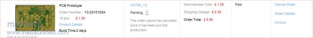 Here are the gerbers - remember - untested as yet!!!!!! 2018-12-16_190809_HAT64.zip The latest schematic 2018-12-16_191048_HAT64_-_Project.pdf and the design files (DesignSpark 8.1) 2018-12-16_191219_Design.zip 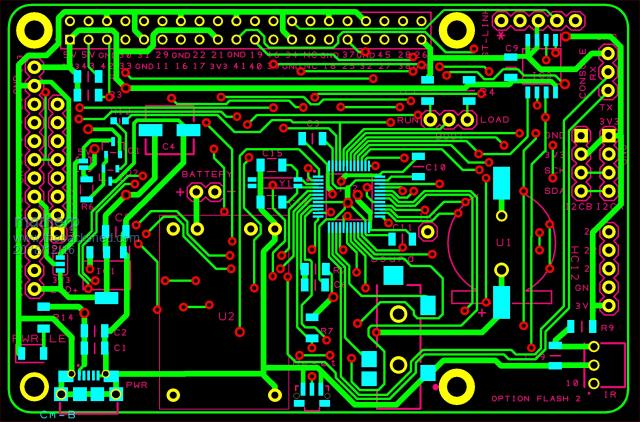 |
||||
| sagt3k Guru Joined: 01/02/2015 Location: ItalyPosts: 313 |
Hi matherp Where do You order PCBs,generally? Thanks Antonio |
||||
| matherp Guru Joined: 11/12/2012 Location: United KingdomPosts: 11166 |
Currently using JLCPCB |
||||
| lizby Guru Joined: 17/05/2016 Location: United StatesPosts: 3733 |
Very cool. How come your shipping price was �5.39 whereas mine from them two days ago was $17.55 with no special instructions (rhetorical)? I tried the solder flood-and-wick-up method on a 48-pinner recently, and bent a pin and soldered it to its neighbor. So I think I need to up my gear. What do you use in the way of iron and magnification? I think this would be hard for me in any case: 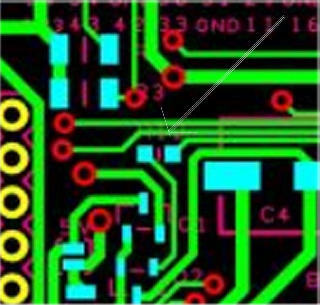 That whole area in fact. PicoMite, Armmite F4, SensorKits, MMBasic Hardware, Games, etc. on FOTS |
||||
| matherp Guru Joined: 11/12/2012 Location: United KingdomPosts: 11166 |
I choose epacket rather than DHL slower but much cheaper and never get hit for import duty 3X desk magnifier and standard fine tip soldering iron. The most important bit is using very fine solder (lead!!!!!) - mine is 0.25mm diameter. I never use the flood technique - just solder each pin individually, normally get 3 pins per dab of solder. I solder the pins on the far side of the chip and stroke the iron from the chip and away, never towards the chip so pins don't get bent. I then use fine 2mm solder braid to clear up any shorts but normally there are never more than 1 or two on a chip. Use liquid flux while soldering (the clear water-like stuff) 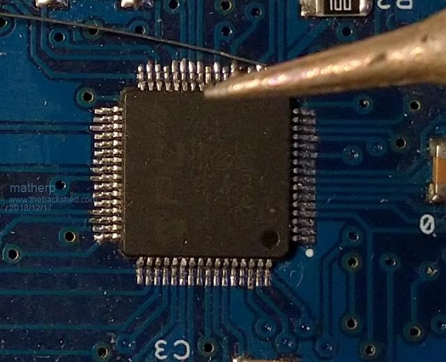 The SOT transistors are easy - just tin one pad and then place the transistor onto the pads hold it down and re-melt the one pad, adjust the position until correct then solder the others. There is an error in that area in that the resistor is 0805 rather than 1206 - well spotted. Corrected in these gerbers 2018-12-17_010710_HAT64.zip |
||||
| lizby Guru Joined: 17/05/2016 Location: United StatesPosts: 3733 |
Much better. What are the small pads below that resistor? Is something to be soldered there? PicoMite, Armmite F4, SensorKits, MMBasic Hardware, Games, etc. on FOTS |
||||
| matherp Guru Joined: 11/12/2012 Location: United KingdomPosts: 11166 |
They are the SOT transistors for the PWM backlight control - can be omitted but they really are very easy |
||||
| matherp Guru Joined: 11/12/2012 Location: United KingdomPosts: 11166 |
The PCBs have arrived and one has been built 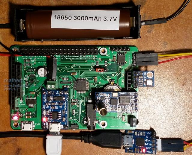 Pretty much everything seems to work but I'm making a few changes for the next release The biggest issue is the the LCD backlight cannot be used on battery power as the supply to the PWM PMOS output FET was taken from the incoming 5V supply rather than the battery output. The connector for the battery is inconvenient and this will be moved to the edge of the PCB next to the IR receiver. Additional pads will be added to support direct connection of BME280 modules and a bigger range of displays. I'm changing the 3.3V regulator to one with a lower drop-out voltage and this has a different pinout. I'm adding holes for a through hole 32KHz crystal as well as the SMD version (this is the long black device by the processor and is a bugger to solder. Other than that the PCB works well and the battery charger/protection module integrates as expected (The red LED in the picture shows it is charging, blue when charged). The other LED just shows that external power is supplied. As with all STM32L4 devices the Armmite firmware can be programmed over the UART connection with no special hardware required although I have added a ST-LINK header. The second picture shows the PCB on battery power with a BMP180 sensor reading temperature and pressure and an HC12 radio module communicating back to a base station. Local display is on a Nokia 5110 LCD. 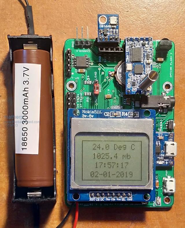 I'll post revised gerbers once I finish evaluating the PCB |
||||
| WhiteWizzard Guru Joined: 05/04/2013 Location: United KingdomPosts: 2962 |
That is shaping up really nicely Peter!  |
||||
Grogster Admin Group Joined: 31/12/2012 Location: New ZealandPosts: 9934 |
The 18650 battery is only 3v7. Are you running this board on 3v7, or does the charger module step this up to a 5v output that you then feed into the main on-board regulator? If the former, then 0.4V is not a lot of headroom.... Smoke makes things work. When the smoke gets out, it stops! |
||||
| matherp Guru Joined: 11/12/2012 Location: United KingdomPosts: 11166 |
That is why I'm changing the regulator to one with a 90mV dropout voltage. More importantly the 1117s have a 5mA quiescent current, hopeless for battery use. I'm moving to the TPS79933QDDCRQ1. At the low currents The PCB will be using this will allow the battery to be used almost 100% with good regulation 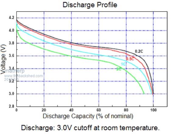 |
||||
| Grogster Admin Group Joined: 31/12/2012 Location: New ZealandPosts: 9934 |
Okey dokey.  I only ask, as I know you can now get 18650 charger module things, that charge the battery AND boost it's output to 5v when not charging - very attractive. Basically what's inside one of those USB powerbank things. Smoke makes things work. When the smoke gets out, it stops! |
||||
| matherp Guru Joined: 11/12/2012 Location: United KingdomPosts: 11166 |
Posts overlapped - see chart above |
||||
| Page 1 of 2 |
|||||
| The Back Shed's forum code is written, and hosted, in Australia. | © JAQ Software 2026 |
