
|
|
Forum Index : Microcontroller and PC projects : Simple LiIon charger for MM projects...
| Page 1 of 2 |
|||||
| Author | Message | ||||
Grogster Admin Group Joined: 31/12/2012 Location: New ZealandPosts: 9935 |
Howdy folks.  I whipped this unit up out of cheap modules from AliExpress and eBay. 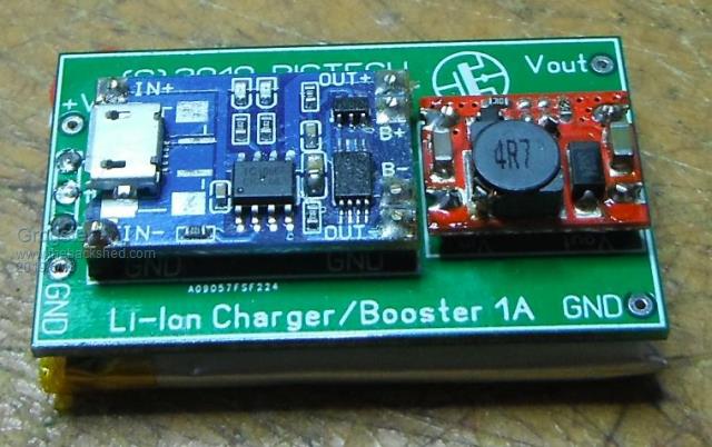 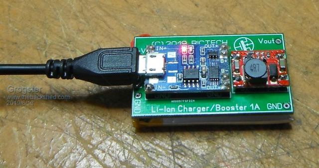 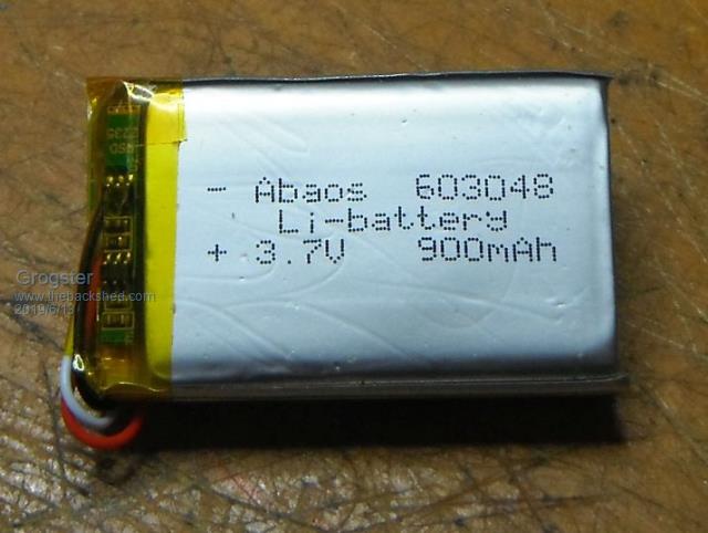 I designed it to be a simple and cheaper alternative to using recharageable 9v batteries, and it is ABOUT the same size as a standard 9v cell. It is SLIGHTLY larger though, but still quite small and includes fully automatic charging module, which is then coupled to a small boost-converter module, and the final output is 5v. Load can be up to 2A, but I am derating that back to 1A just to give me a little headroom. I have had 500mA load on this for several hours no problem, but more then that at 100% duty, and the little boost-converter gets quite hot. I never need anything like 2A @ 100% anyway, as this is designed as a replacement for some battery powered things, so the normal current consumption is much, much less then that. The host PCB(green) holds the charger module, which is based on a TP4056 1A Li-Ion battery charger IC. The module I am using also incorporates under-voltage protection, and conveniently has a micro-USB socket at one end, so charging the battery is as simple as plugging in a suitable USB cable. The charger module has two LED's on board, one is red when charging, and the other is green which lights when the battery is charged. The red one goes out when the green one lights. These signals could easily be harnessed by the MM circuit, to know when the battery is on charge, and/or when it has finished charging. The boost-converter is designed to be connected to a 3.7v battery, and to provide 5v output, and is based on an MT3608 boost-converter IC. This is ideal for feeding into many MM circuits, as they also have on-board 5v-to-3v3 regulators themselves. The charger modules I used were theese ones. The boost-converter modules I used were theese ones. The batteries I used were theese ones. There are a plethora of different size 'Silver-bag' Li-Ion batteries available, and the little green host board setup could be used with any of the bigger batteries too if you wanted. The charger module limits the charging current to 1A. If anyone is interested in the little green host PCB, let me know on this thread. I already plan to add some extra pads along the output edge of the board, to route the LED signals from the charger module via some short links, so that a simple 4-way Dupont wire can provide power and charger state signals to your MM project. Smoke makes things work. When the smoke gets out, it stops! |
||||
| viscomjim Guru Joined: 08/01/2014 Location: United StatesPosts: 925 |
Very nice indeed! Can you charge the battery while under load like ups style? |
||||
| Grogster Admin Group Joined: 31/12/2012 Location: New ZealandPosts: 9935 |
Yes. With a 570mA load on the 5v output, the red charge light comes on and the battery voltage is still sitting at 4.15v which is pretty much exactly right as the nominal is 4.2v. EDIT: Efficiency of the boost-converter gets worse the more you load it up. This is kinda expected with the inductor on-board being kind of generic in value to suit middle-of-the-road kinds of use. Output voltage drops to 4.85v with 570mA load, but is back to 4.95v with a 300mA load. Considering this is for battery-powered use, you would not be running 100% duty-cycle, so while this is showing a little lag when you load it up, this is not the normal way I would use it anyway.  You could probably fix that with some more external decoupling caps on the main MM board. It should certainly be able to handle burst-currents from loads such as the HC12 RF modules etc, which normally are in sleep mode on battery anyway, only waking up to transmit or receive. Smoke makes things work. When the smoke gets out, it stops! |
||||
| matherp Guru Joined: 11/12/2012 Location: United KingdomPosts: 11206 |
Not sure why you want the boost charger. Take 4.2V boost to 5V at say 85% efficiency. Then use linear reg to get 3.3V at 3.3/5*100 = 66% efficiency so total efficiency is 56%. Now lets look at the lipo chemistry. At small/noload a lipo is 95% discharged at a measured voltage of 3.6V. My solution as on the Armmite L4 board is to use just the same charger/protection module and then a ultra low-dropout regulator to get 3.3V. Also critical for battery operations is the leakage of the linear regulator. A normal LM1117 has a quiescent current of 10mA which will quickly flatten a 900mAh battery. Last point your battery pictured looks like it already has built-in under-voltage protection. Doesn't matter but another point of failure. 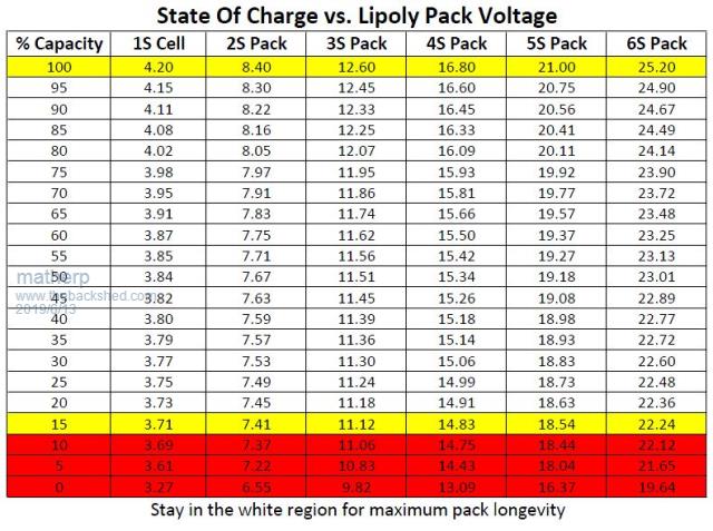 |
||||
| Grogster Admin Group Joined: 31/12/2012 Location: New ZealandPosts: 9935 |
I never said anything about a 'Boost charger'. I said 'Charger module' and 'Boost converter'. When did I say I was ever using a linear regulator to get 3.3v? I said I have a LiIon(3.7v) charger module, which is then coupled to a boost-converter to get the final output voltage of 5v. I was talking about the MCP1703 series CMOS regulators that are in all MY battery-powered stuff, and in pretty much ALL my designs. They have a quiescent current of about 200 micro-amps. Certainly nothing like in the area of 10mA or so of a linear. If you elect to connect this to a linear regulator such as the 1117 with a quiescent current of 10mA or more, that is not MY problem.  Battery having in-built under-V protection: That could be a valid point, I will investigate that side of things. Smoke makes things work. When the smoke gets out, it stops! |
||||
| matherp Guru Joined: 11/12/2012 Location: United KingdomPosts: 11206 |
Can't find a reference to this. Please could you point me at one - thanks Sorry, my lazy typing; I was talking about the boost converter which is the bit I don't understand the need for. |
||||
| Grogster Admin Group Joined: 31/12/2012 Location: New ZealandPosts: 9935 |
Sorry if I came off a bit curt - I am on the home-brew tonight... I use the MCP1703 series regulator for most of my stuff. They make them in most common output voltages. Here is a direct link to the PDF for these regulators. They are my go-to regulator. I would never touch a linear for anything battery powered - they are just too thirsty as you would probably agree. EDIT: I need 5v at the input to most of my battery powered stuff, as I use HC12 RF modules for most of that stuff, and it needs 5v. It is unreliable at 3v3. If all I needed was 3v3, then yes - you could just direct-connect the 3.7v battery to the 1703 regulator to get 3v3. Smoke makes things work. When the smoke gets out, it stops! |
||||
| matherp Guru Joined: 11/12/2012 Location: United KingdomPosts: 11206 |
Now I'm really confused. I think/thought the MCP1703 WAS/IS a linear regulator. i.e. the difference between the input voltage and the output voltage multiplied by the current being passed is given off as heat. It happens to be CMOS and have high internal efficiency but the main power loss still applies. From Microchip AN765 (Using Microchip�s Micropower LDOs) power dissipated = (Vin-Vout) * Iload + (small bits related to bias supply current) |
||||
| twofingers Guru Joined: 02/06/2014 Location: GermanyPosts: 1733 |
Hi Grogster, the MT3608-datasheet says the Quiescent Current is what is your measurement? Maybe interesting: the MT3608-PIN 4 is the "Regulator On/Off Control Input." or EN(able). BTW. I had the same idea a few months ago.  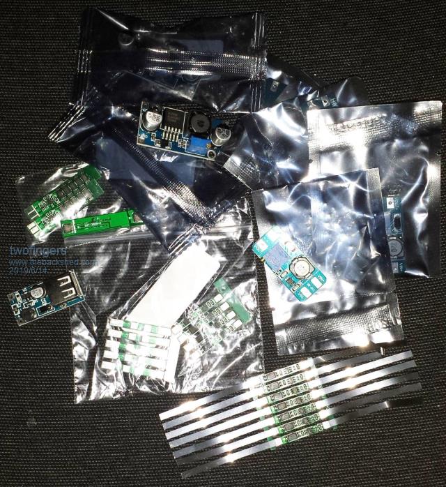 Kind regards Michael causality ≠ correlation ≠ coincidence |
||||
| CaptainBoing Guru Joined: 07/09/2016 Location: United KingdomPosts: 2171 |
The charger is the perfect accompaniment to the wireless charger units... very handy - ta |
||||
palcal Guru Joined: 12/10/2011 Location: AustraliaPosts: 2039 |
I saw these on TBS some time back, think it may have been BigMick, Here I have a few of them, only thing is you can't connect in and out at the same time but the price is right. Edit...oops that's not the ones I have mine have an LCD screen Here "It is better to be ignorant and ask a stupid question than to be plain Stupid and not ask at all" |
||||
| lizby Guru Joined: 17/05/2016 Location: United StatesPosts: 3740 |
For the 18650 battery (not the form factor Grogster is looking at), I've found these to work as a UPS, powering and charging simultaneously: 18650 UPS They include a 3.3V output (I haven't checked on its efficiency. The drawback that I have encountered is that if the low-voltage dropout is activated for 5V, it won't turn back on unless you flip the switch off and on. I'd like to see a module which has an output to indicate that dropout is about to occur, so that something like the raspberry pi can shut down gracefully. PicoMite, Armmite F4, SensorKits, MMBasic Hardware, Games, etc. on FOTS |
||||
| Grogster Admin Group Joined: 31/12/2012 Location: New ZealandPosts: 9935 |
@ matherp - you may be right, when I re-study the datasheet for the 1703's. Their quiescent current is 2uA(not 200uA as I said above), so that is a very good quiescent figure, and I must have been confusing the 1703 and the boost-converter quiescent figures. I had had a few pints of home-brew by that state. Probably should not drink and post.... However, having said that, with everything in sleep mode(the HC12 module and the MM chip), the current drawn is only in the area of 40-45uA or so from the circuit, so factor in the 170uA of the boost-converter - 215uA or so idle current, so that is good enough. For ME. Others who love to push the boundaries of how long they can make their batteries last, won't agree with me here.... Oh well. EDIT: This battery life calculator says that with a 900mAh battery and a 200uA load, the battery will last for 3,600 hours with a 20% discharge safety - or 150 days / 21.4 weeks. Naturally, that is if the circuit stays asleep all that time, but about five months in standby is good enough for me. Change to slightly juicer batteries and the figures would get even better. I could not get anything LIKE this time on 180mAh 9v rechargable batteries, so.... My ones have a quiescent current of 170uA at idle. Yes, I actually used them on those when I was playing with them a few weeks ago. The only problem I experienced was lack of current transfer on the wireless charger thing. I had a 5W one. I am going to get a 10W one to see if that helps. Charging current on the wireless setup was measured as only 200mA or so at best. If you are not in the sweet-spot on the charger base, the coupling fails completely or drops so much that the charger module is dropping in and out of operation. Not completely convinced on the wireless charger things yet. Yes, me too. That's the only annoying thing about the auto-dropout - you don't know it is going to happen. I guess you could put a potential-divider across the battery and read the voltage with an ADC pin, and if it gets close to 2.2v, then assume.... Smoke makes things work. When the smoke gets out, it stops! |
||||
| lizby Guru Joined: 17/05/2016 Location: United StatesPosts: 3740 |
I'm confused about the low-voltage dropout point. Matherp's chart indicates that it should occur at no lower than 2.73V with 20% remaining. But is that a "no-load" voltage? I've read elsewhere that under load, 2.5V is a good cutoff (but it depends on the current being drawn). (And I've also read that no lower than 40% is best for the life of the battery through many charge/discharge cycles.) Does the chart apply to both 18650s and the form factor that Grogster is using? And there's the question of different Lipo chemistries, which result in different ideal low-voltage dropout points. How about with something like the 18650 charger/ups that I linked to, powering the micromite/pi from the 3.3V output (which I think doesn't drop out), and monitoring the 5V output for the dropout, which would allow the device either to power itself off or send a "low-voltage" warning. That still wouldn't fix the problem of the battery module having to be power-cycled to turn the 5V back on after a low-power shutdown. PicoMite, Armmite F4, SensorKits, MMBasic Hardware, Games, etc. on FOTS |
||||
| paceman Guru Joined: 07/10/2011 Location: AustraliaPosts: 1329 |
I too bought a couple of the XC4052 charger modules and XC4512 boost modules six months ago but on looking into it a bit further became nervous about my 18650's. My XC4052 modules came fron Bangood but look exactly like yours Grogs, blue PCB but without the fancy logo on the back. I managed to decipher the IC designations on them and these were: TP4056 - Charger IC ML8205A - Dual Mosfet, v. low RDS(ON), common drain DW01A - Battery protection IC, cutoff 2.4v (way too low). Alternative is FS312F/G with 2.9v cutoff (still too low) Somewhere (haven't been able to find it again) I read that when using the module to supply a load (connected to the OUT terminals) with the connected battery, the DW01 battery protection IC doesn't cut off the battery supply (via the MOSFETS) until its voltage drops to 2.4v. This is way too low for a Li ion/poly battery and will soon ruin it. The writeup suggested to use the 'alternative' FS312F/G battery protection IC shown above which has a 2.9v cutoff but to me this is still much too low. I downloaded the manufacturer's (Fortune IC) datasheets which confirm these cutoff voltages. I went ahead and bought some of the FS312's anyway (e-Bay this time, US$2.70 for 10 off), and actually managed to swap one with the DW01 on one of the modules - no small feat with a SOT23-6 package I can tell you! I intended to run one of my 18650's down and monitor what happened but so far I've chickened out in case I damage it. The module charged the 18650 nicely and did all the right things charging (current limiting and O/V cutoff) but leaving it connected with a load on the OUT terminals is a bit iffy to me. Greg |
||||
crez Senior Member Joined: 24/10/2012 Location: AustraliaPosts: 152 |
I have been running a solar powered 'mite with a LiPo battery from a mobile phone directly connected to the 'mite. The only regulator is a TL431 shunt regulator that stops the battery charging above 3.85v so the 'mite doesn't blow up. It means I'm only using about 1/3 of the capacity of the battery, but it is doing the job so far. I was a bit concerned that the slow ramp-up in the voltage after a long night would not allow a proper reset but it works OK. It spends most of it's time asleep, waking every 10 seconds to send some data on a wireless link. |
||||
| Tinine Guru Joined: 30/03/2016 Location: United KingdomPosts: 1646 |
Count me in for a bunch  |
||||
Quazee137 Guru Joined: 07/08/2016 Location: United StatesPosts: 603 |
I stuck one of them on the back side of a mite that needed to stay alive for a day or two if mains went out. 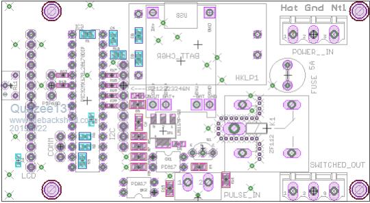 |
||||
| Grogster Admin Group Joined: 31/12/2012 Location: New ZealandPosts: 9935 |
Latest version image: 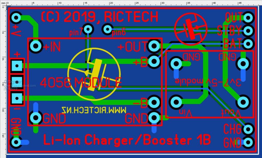 Simple five-wire interface to your MM project: OUT - Main output. Connect this to your MM project Vin. STBY - 4056 charger IC standby LED output(pin7). BAT - Positive of LiIon battery. CHG - 4056 charger IC charger LED output(pin8). GND - Ground. STBY and CHG must be connected to 5v tolerant MM pins, as they are active-low, being pulled high to V+ and going low when they are active. I recommend still using 1k series resistors on these two signal lines. BAT is the positive of the LiIon battery pack. You can measure the battery voltage with an ADC pin on the MM. You should use a 5v pin for this also. Smoke makes things work. When the smoke gets out, it stops! |
||||
| Lightrock Newbie Joined: 19/05/2014 Location: AustraliaPosts: 26 |
I will take 3 thanks Grogster |
||||
| Page 1 of 2 |
|||||
| The Back Shed's forum code is written, and hosted, in Australia. | © JAQ Software 2026 |
