
|
|
Forum Index : Microcontroller and PC projects : Help with FM radio and PCB design
| Author | Message | ||||
| Benzol Regular Member Joined: 07/01/2015 Location: AustraliaPosts: 64 |
Hi all. I'm building the FM clock radio submitted by Dan Amos in Silicon Chip. I thought it was going to be an easy build with Vero board, however the size and shape of the modules made for a very messy result and difficult to squeeze into a decent sized box with a screen and MM backpack. So I decided to try PCB design software. Fritzing looked good except for the limited standard components and PCB layout once the schematic was designed. I researched what others on this forum use, DEXPCB, Sprint Layout, Diptrace, Eagle, Design Spark and Protel 99 were just some in use. Everyone has their favourites. What is simple to use, covers a decent spread of components and good for just small jobs? Thanks in advance everyone. db |
||||
| lizby Guru Joined: 17/05/2016 Location: United StatesPosts: 3008 |
Design Spark and Diptrace are quite popular now, and either would probably be a good place to start. I have used Eagle for a good many years because I am familiar with it, but its eccentricities are well known and can be confounding for beginners (and for me when I try something new, like designing a new part). PicoMite, Armmite F4, SensorKits, MMBasic Hardware, Games, etc. on fruitoftheshed |
||||
palcal Guru Joined: 12/10/2011 Location: AustraliaPosts: 1796 |
There was another post about this by DAVEMATT He may be able to help in some way. "It is better to be ignorant and ask a stupid question than to be plain Stupid and not ask at all" |
||||
| morgs67 Regular Member Joined: 10/07/2019 Location: AustraliaPosts: 70 |
Hi Benzol I am having fun with this as well. I am building this on a V3 backpack fitted with the clock chip and backup battery. By using the mute pin on the amplifier board the amplifier can be turned off, saving using the relay circuit. Using a piezo buzzer off the backpack, no audio switch ic is needed (I am not using line in). Resizing all the windows and buttons for the larger screen took some time. The TEA5767 module seems a little deaf. I have a Si4703 which works much better, but it is on an arduino. Present task is translating the C+ to MMBasic so I can use it. |
||||
| Benzol Regular Member Joined: 07/01/2015 Location: AustraliaPosts: 64 |
Hi Paul and Lizby. Thanks for the feedback, I will try to contact davematt to see how he constructed it. Morgs, have you built the circuit on a PCB or stripboard? thanks |
||||
| morgs67 Regular Member Joined: 10/07/2019 Location: AustraliaPosts: 70 |
No circuit board at present. Random frequencies are a result of autotune being set on. This is fixed by at line 566 removing " or &h40 " Set lowest frequency to 87.50 instead of 88.00 in a couple of places. At line 180 replace b(b,3) with win(b,3) |
||||
| Pinboards Newbie Joined: 19/08/2019 Location: AustraliaPosts: 3 |
I have used 'FreePCB' for many years now. It works well with no glitches, no size limitations and is not over complicated like some of the others (including many expensive programs). http://www.freepcb.com/ We use it in a commercial environment with great success. It certainly does everything we need quickly and easily. I'm advocating FreePCB because it seems to fall between the cracks and not many are aware of it. I have tried all the usual suspects, Kicad, Diptrace, Altium (purchased at great expense)and others and they always seem to have some limitation - max number of pads (unless you buy it) or some crazy file types. Some have a learning curve that I'm not interested in following. FreePCB generates bog standard Gerber files that are accepted by every Chinese board house we have used over the past 5 years without question. A note that it is written for Windows so AFAIK no Apple version. One of our larger boards that we designed using FreePCB: 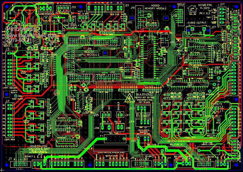 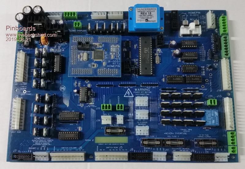 |
||||
| Benzol Regular Member Joined: 07/01/2015 Location: AustraliaPosts: 64 |
Hi Pinboards Thanks for that. I'm trying the free version of Diptrace at the moment. Freepcb is not one that I came across so it's definitely worth a look. That is a very complex board board you have there. Regards |
||||
