
|
|
Forum Index : Microcontroller and PC projects : CMM: How sharp should the VGA output be?
| Author | Message | ||||
| thwill Guru Joined: 16/09/2019 Location: United KingdomPosts: 4360 |
Hello folks, I've just finished building my Colour Maximite (thanks to Phil @ www.micromite.org) and fired it up for the first time attached to a VGA monitor. The image does not the crystal clarity I have come to expect from modern computers, is this to be expected? There is nothing I can sucessfully capture on camera but characters seem to have a very slight blur to them, more noticeable in Mode 4 than Mode 3. I guess the image is still probably better than I remember from an 8-bit computer attached to an old TV, but I'm wondering if it something I haven't managed quite correctly in the construction. Any opinions/suggestions? Tom MMBasic for Linux, Game*Mite, CMM2 Welcome Tape, Creaky old text adventures |
||||
| ceptimus Senior Member Joined: 05/07/2019 Location: United KingdomPosts: 130 |
Have you tried different VGA cables? I swapped a cheap one for a quality one and that resulted in a huge improvement in picture quality. |
||||
| MauroXavier Guru Joined: 06/03/2016 Location: BrazilPosts: 307 |
I believe that you are talking about the scaling of the pixels that aren't perfect because the CMM doesn't use a standard resolution, and you are using a modern digital display. Enter in your monitor menu and check what resolution is displaying, and you see that the scale factor is not an integer. Per example: Mode 1 to 3 - CMM 480x432 -> Monitor 640x480 Mode 4 - CMM 240x216 -> Monitor 640x480 I recommend to force to 4:3 aspect ratio (if your monitor has this option) and use manual adjustments to improve the image quality, but you probably will lose the fullscreen. But if you use a CRT monitor, the image will display crystal clear due to the nature of analogic scaling. Edited 2019-09-17 00:41 by MauroXavier |
||||
| MauroXavier Guru Joined: 06/03/2016 Location: BrazilPosts: 307 |
I almost forgot another thing about the CMM that can compromise the image quality in some monitors. The image generated by the CMM is entirely made by software without VSYNC, and the pixels sometimes can appear somewhat misaligned to show colour in a digital display (again, this not occurs in a CRT), creating a little "colour shadows" around the pixels. In any case, this doesn't occur in all digital displays, this depends on how the display processor treats the signal. |
||||
| thwill Guru Joined: 16/09/2019 Location: United KingdomPosts: 4360 |
Thanks, this does sound like what I am seeing. In any case I've tried a different LCD monitor and a different cable and that doesn't seem to be the problem. I don't have a CRT. MMBasic for Linux, Game*Mite, CMM2 Welcome Tape, Creaky old text adventures |
||||
| ceptimus Senior Member Joined: 05/07/2019 Location: United KingdomPosts: 130 |
Are you sure you assembled the Maximite with the correct resistors and the diodes the right way round on the VGA output part? The idea is that the red, green, and blue pins for VGA vary between 0V and 0.7V. �Because the CMM is only eight-colour, it wants those pins to be either high or low, and it does this by using relatively low value resistors (120-Ohm) with 1N4148 diodes that clip the maximum voltage at or below 0.7V. If you use slower diodes then they don't switch fast enough and that results in a fuzzy picture. �If you've fitted one or more of the diodes backwards, then the voltage will be driven above 0.7V which is outside the VGA spec and also results in a poor picture. �The black bands on the 1N4148 diodes should be on the side nearest to the voltage regulator. 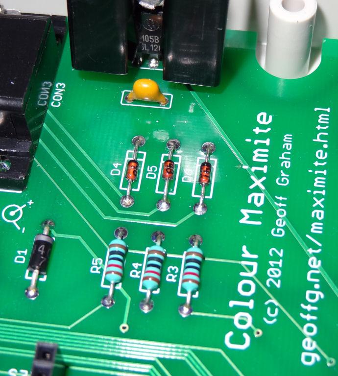 Also, it's easy to fit resistors with too high a resistance that will produce a feeble, dimly-coloured picture. Those four-band resistors are a nightmare. �Depending on which end you read them from, Brown, Black, Black, Red, (Brown) is 10K with the last Brown meaning 1% tolerance, but from the other (correct) end, Brown, Red, Black, Black (Brown) is 120 ohms, also 1% tolerance. I almost always check the resistance of resistors using a trusted multimeter - apart from the stupid ambiguous colouring scheme, I've seen resistors that were just totally wrongly coloured: I've kept one somewhere that is almost exactly 220 ohms (should be red, red, black, black, brown) but is actually painted yellow, violet, black, red, brown - 47K! Make sure you have the correct 120 ohm ones fitted (150 ohm would also be okay). . Edited 2019-09-17 03:06 by ceptimus |
||||
| thwill Guru Joined: 16/09/2019 Location: United KingdomPosts: 4360 |
Thanks Ceptimus, I'll check all this when I can escape from the family for 30 mins ;-) All the parts came with the kit from micromite.org and I tested the resistances as I installed so I'm reasonably certain I've got it right ... and would expect more obvious prolems if I hadn't. To be honest I think Mauro had the correct explanation. And I agree regarding the resistors, much prefer the kharki coloured ones. MMBasic for Linux, Game*Mite, CMM2 Welcome Tape, Creaky old text adventures |
||||
Chopperp Guru Joined: 03/01/2018 Location: AustraliaPosts: 1121 |
I have to give my VGA connectors a bit of a wriggle every now & then if the picture goes a bit funny. ChopperP |
||||
| ceptimus Senior Member Joined: 05/07/2019 Location: United KingdomPosts: 130 |
I've used my CMM on several LCD monitors, and the picture is pretty sharp - better than most vintage computers from the 8-bit era, but not as sharp as modern kit. �I also tried my CMM on an old CRT display and it didn't look any better. I agree with Mauro about playing with the monitor menu settings - especially to try and get a 4:3 aspect display. �On a modern 16:9 or wider monitor, that will leave you with black bars up both sides of the display, of course - but you'll be seeing the picture that Geoff, the CMM designer, intended. [aside] CMM pixels aren't square, even with a 4:3 monitor - they're wider than they are tall, height being about 83.3% of width. �Their width:height ratio is 6:5 The non-square pixels are the reason I wrote my PTETRIS program in Mode 3 - that way I could make the tiles 18 pixels high and 15 pixels wide to make them appear square on standard monitors. �In mode 4, I couldn't make them square and keep them a reasonable size. [/aside] Here are some photos I just snapped of the screen. This is with a cheap Acer KA220HQ LCD monitor. I really should have wiped the dust off the screen first!  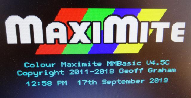  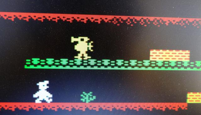 . Edited 2019-09-17 22:07 by ceptimus |
||||
| MauroXavier Guru Joined: 06/03/2016 Location: BrazilPosts: 307 |
Your LCD has a very stable image, but when I say about the quality, we can see in the image below the irregular scaling effect:  Look in the M letter, you will see that the vertical lines are not the same width for the same letter in another position on the screen. The letter X has the same problem, which doesn't have uniformity in the diagonal lines, and I sure that the same letter in another position will sometimes have perfect diagonal pixelated lines. This is not a CMM bug, it's like I said before, it's just the digital display trying to scale a not standard resolution, and on an analog display, these scale effects don't occur. I used very old LCD monitors on the CMM, and some have a little color shadows effect with some small flickering, and others have a perfectly stable image. Only on a CRT I see a crystal clear image without any scaling misalign, but when I use blit command to scroll colored images too fast it's possible to see the colors out of sync because the CMM doesn't put the three colors at exact same time and doesn't use VSYNC or a frame buffer. Edited 2019-09-18 04:06 by MauroXavier |
||||
| Warpspeed Guru Joined: 09/08/2007 Location: AustraliaPosts: 4406 |
You might be surprised that there are over sixty different VGA standards with different timings and resolutions. http://tinyvga.com/vga-timing Most better LCD monitors measure the input signal and retrieve the correct display parameters from an extensive lookup table. It usually works fine, or may come up with an error message. Or it may just try to display what is there, often with less than wonderful results. Cheers, �Tony. |
||||
| ceptimus Senior Member Joined: 05/07/2019 Location: United KingdomPosts: 130 |
Even an analogue screen (a colour one anyway) will show some distortion if the pixel clock rate doesn't agree with the monitor's horizontal beam speed compared to the spacing of its phosphor dots (and the grid the beams pass through to hit the dots). It's possible that the phosphor dots on a colour CRT are smaller and closer together than the pixels on an LCD screen so the effect is less obvious. The chances of the pixel clock being perfectly aligned with the phosphor dots over the whole screen is pretty negligible. My old CRT has adjustments for horizontal and vertical size and position, skew, rotation, trapezoid, and barrel/pincushion, but even after tweaking all those I can never get it absolutely right. |
||||
| thwill Guru Joined: 16/09/2019 Location: United KingdomPosts: 4360 |
I've checked the diodes and resistors, and I've wiggled the connectors to no avail, pixels (especially in Mode 4) still have a "shadow": 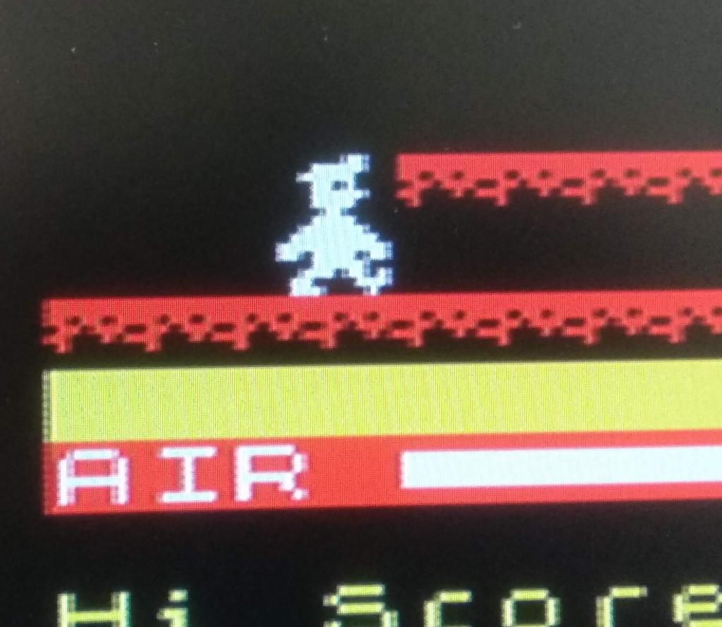 Nice work on Manic Miner by the way ceptimus. MMBasic for Linux, Game*Mite, CMM2 Welcome Tape, Creaky old text adventures |
||||
| ceptimus Senior Member Joined: 05/07/2019 Location: United KingdomPosts: 130 |
Maybe try a different power supply for the Maximite? You can temporarily run it from one of those phone power bank battery things - which eliminates any earth loop interference. If that makes no difference, I suppose the only thing left to try is other monitors or TVs that have a VGA connection. |
||||
| Volhout Guru Joined: 05/03/2018 Location: NetherlandsPosts: 5781 |
dear thwill, The picture you did send makes me expect that you are using an LCD TV capable of receiving old analog TV signals (connected to VGA), not an LCD monitor (connected to VGA). The TV video processor is capable of processing an interlaced signal (i.e. 480i). The interlaced signal (appart from alternating between odd lines and even lines) has a small delay on the even lines. That may be visible in your picture. That also could explain the shift in color. If I where to guess, this is an LCD TV, not a monitor. Appart from that there will be sampling problems in the LCD A/D convertor due to the different resolutions. More expensive LCD's will be capable of oversampling and aligning better, but the 640x480 LCD's (chipsets) will show artefacts. The maximite also cut's a corner with the VGA output impedance. There is nothing you can do about this in the current design, but to create analog VGA from a 120 ohm resistor and a diode gives a rather strange (*) output impedance (not 75 ohm). With long cables you may see reflections in the cable, giving visible artefacts. Volhout (*)= When driving 0.7V, the diode conducts, and causes 5 ohm output impedance (25 ohm / current in mA), when driving 0V, the diode is open, and your output impedance is 120 ohm + IO pin resistance. PicomiteVGA PETSCII ROBOTS |
||||
| thwill Guru Joined: 16/09/2019 Location: United KingdomPosts: 4360 |
Thanks Volhout, I appreciate you taking the time to reply. You are correct, it is an LCD TV, one with a bunch of connections (inc. SCART) that I acquired for attaching retro computers to. I did briefly test the Maximite on a more modern LCD monitor earlier in the week and thought I'd seen the same problem ... ... I'll check again tonight/tomorrow. Tom Edited 2019-09-20 01:48 by thwill MMBasic for Linux, Game*Mite, CMM2 Welcome Tape, Creaky old text adventures |
||||
| cosmic frog Guru Joined: 09/02/2012 Location: United KingdomPosts: 307 |
It's normal, mine is exactly the same. I think it's because the three signals (RGB) arrive at the monitor at slightly different times. You can't see it as much on a CRT monitor and it's not as bad on higher resolutions. Dave. |
||||
| Frank N. Furter Guru Joined: 28/05/2012 Location: GermanyPosts: 1057 |
It makes a difference to me whether I press the reset button or switch on the power again. It is exactly the problem that Dave describes! I think I remember a re-power-up was better... Frank |
||||
| The Back Shed's forum code is written, and hosted, in Australia. | © JAQ Software 2026 |
