| Author |
Message |
MustardMan

Senior Member

Joined: 30/08/2019
Location: AustraliaPosts: 175 |
| Posted: 10:33am 01 Oct 2019 |
 Copy link to clipboard Copy link to clipboard |
 Print this post |
|
Hi,
Micromite Explore 100 with 5" SSD1963 800x480 display, resistive touch, MM-BASIC v5.
My wish is to create a device that looks somewhat more "tailored" or "slick" than the usual 16:9 displays that are very easily available. To that end I've been developing using a standard 5" display, but, I intend on progressing to a 'super wide' LCD before too long.
I purchased what is advertised as a "bar" display from buydisplay.com (for the interested, https://www.buydisplay.com/default/4-6-inch-color-bar-tft-lcd-iot-display-800x320-pixels-with-optl-touch-screen ). It is a "bare" LCD with just a 40 pin ribbon...
I wondered if the Explore 100 MM-BASIC firmware could be altered to drive this LCD. I looked through the source code, and pondered if it would be as easy as changing the "DisplayVRes = 480" in the file "MicroMiteSource.zip\Source\MX470\SSD1963.c". I asked Geoff and he suggested it probably wouldn't be so simple... there are a stack of parameters required to drive an LCD properly!
I had one to try, and it had the same ribbon connector as the 800x480 LCD... what could possibly go wrong!
So I plugged it in, and to my surprise it actually worked! Only the bottom 320 vertical pixels were displayed, but the full 800 horizontal pixels were visible.
The next step is setting up a compiler chain and making a tweak or two to the firmware to see what happens... |
| |
MustardMan
Senior Member
Joined: 30/08/2019
Location: AustraliaPosts: 175 |
| Posted: 01:43am 12 Oct 2019 |
Copy link to clipboard |
Print this post |
|
Frustrating... I've made tweaks to the MMbasic firmware (SSD1963.c and associated), but no matter what I do, the display does not operate correctly.
First test was to see if changing the firmware would work, and it appeared promising. When setting the Vertical size to 320 (my panel size), it displayed as expected on a 800x480 panel.
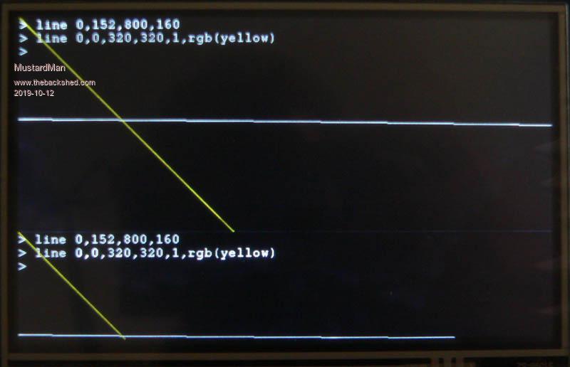
160 lines of the top section (800x320) are repeated from 320 to 480.
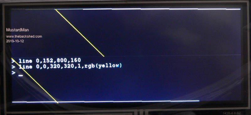
However, when I attach the genuine article, the 800x320 display, it displays the bottom section of what would notionally be a 800x480 screen, but all the rendering for a 320 height screen is performed correctly!
I've tweaked the pixel clock, the horizontal (and vertical of course) sync, the sync polarity, front & back porches (with absolutely no change to the display), and in desperation have started looking at other 1934 commands to tweak.
Any insight as to what is going on?
Cheers,
Edited 2019-10-12 12:41 by MustardMan |
| |
MustardMan
Senior Member
Joined: 30/08/2019
Location: AustraliaPosts: 175 |
| Posted: 09:33am 14 Oct 2019 |
Copy link to clipboard |
Print this post |
|
Well, I've decided to go the 'dirty hack' way and simply plug the 800x320 'wide screen' display in in place of the 800x480 standard display and perform all my display operations (graphical only, no text) using the bottom "half" of the screen. ie: add 160 to all "y" co-ordinates (160 = 480 - 320).
I've already spent two full days trying to find the cause of the problem, and I am not willing to spend any more.
I've written to "buydisplay.com", but despite their website promise ... Of course, we wouldn't just leave you with a datasheet and a "good luck!" ... I don't hold much hope in getting a useful response. I might look further in my spare time (because I don't like to be beaten by "the tech"), but apart from that, I think a 'dirty hack' is gonna have to do.
I suspect the SSD1963 is not reconfiguring the H & V timers as I am asking it to, because even drastic changes to the parameters make no visible changes to the display. I will have to break out some thin wires to a cro to find out.
I also think the SSD1963 might be refreshing the display from the bottom up, which would explain why it shows the bottom part of a 800x480 image rather than the top. The cro will verify that too.
Cheers, |
| |
MustardMan
Senior Member
Joined: 30/08/2019
Location: AustraliaPosts: 175 |
| Posted: 09:44am 30 Oct 2019 |
Copy link to clipboard |
Print this post |
|
BuyDisplay got back to me... after I sent them a reminder. The very same day I sent them the reminder in fact! The first response got lost, to which they apologised for.
They explained, and with a bit of interpretation on my part, that the 'superwide' (800x320) TFT glass is exactly the same as the standard (800x480) TFT glass, it uses the same ILI6122 chip-on-glass controller, and with exactly the same parameters. The glass is simply "missing" the top 160 rows of pixels.
Hence, the "dirty hack" that I talked about was/is actually the correct way to access this display!
Pity it is the top 160 pixels missing and not the bottom. That would have made driving it a whole lot easier (not having to add 160 to every Y co-ordinate).
Also, in case anyone is interested, this display is refreshed from top-to-bottom, but not interlaced like a CRT TV is. Apart from that, it uses almost the same H/V timing.... V~60Hz, H~2x15kHz.
Cheers. |
| |
MustardMan
Senior Member
Joined: 30/08/2019
Location: AustraliaPosts: 175 |
| Posted: 09:44am 30 Oct 2019 |
Copy link to clipboard |
Print this post |
|
BuyDisplay got back to me... after I sent them a reminder. The very same day I sent them the reminder in fact! The first response got lost, to which they apologised for.
They explained, and with a bit of interpretation on my part, that the 'superwide' (800x320) TFT glass is exactly the same as the standard (800x480) TFT glass, it uses the same ILI6122 chip-on-glass controller, and with exactly the same parameters. The glass is simply "missing" the top 160 rows of pixels.
Hence, the "dirty hack" that I talked about was/is actually the correct way to access this display!
Pity it is the top 160 pixels missing and not the bottom. That would have made driving it a whole lot easier (not having to add 160 to every Y co-ordinate).
Also, in case anyone is interested, this display is refreshed from top-to-bottom... V~60Hz, H~2x15kHz (as it is not interlaced).
Cheers.
Edited 2019-10-30 19:52 by MustardMan |
| |
