
|
|
Forum Index : Microcontroller and PC projects : two programming environments for the STM32F4V
| Author | Message | ||||
| poida Guru Joined: 02/02/2017 Location: AustraliaPosts: 1388 |
I've spent a little time playing with a STM32F4VET6 based cheapie from Aliexpress The Arduino IDE does work with this board, but you need to use the ST-LINK programmer. The alternative IDE used was Atollic truestudio for STM32. This is also a free download. The F4 offers hardware floating point support. Until now, I have used the ATMega 328p (Arduino Uno, etc), the Atmel SAM3 (Arduino Due), the ESP32 Wroom and the STM32F1 "Blue pill". All lack floating point hardware. I wanted to see how fast it can go. The task is the Lorenz Atractor, see Paul Bourke's page with code examples The code continuously loops, calculating new values that are then fed back into the loop. If you monitor the variables x0, y0 and z0 you will see lovely chaotic behaviour. feed x0 and y0 into a DAC and then take these to an oscilloscope and you will see the same sort of thing as seen in the web page. You could output these via a serial port and plot them, just as good and easy to do with the Arduino IDE. Measured times for an iteration through the continuous loop: Arduino Due (SAM3, 84MHz): Ā20 usec F4, 168Mhz, Arduino : 6 usec F4, 168Mhz, Atollic : 0.288 usec The F4 is fast. The Arduino IDE is not able to compile code using the floating point hardware, due to included libraries that are precompiled using soft floats. The Atollic IDE can compile code using the floating point hardware, and it can employ optimisation too, and it's good quality. Timing was done using a DSO monitoring a GPIO pin. Anyway, I thought some here might want to get an idea of how good the STMF4 is for the price and the compute power. I paid $9.70 US for it. It's probably the pick of the litter for running MMBASIC on. Here are the codes used. I freely use direct hardware manipulation for digital i/o and DAC access. Arduino DUE char buf[100]; inline void digitalWriteDirect(int pin, boolean val){ Āif(val) g_APinDescription[pin].pPort -> PIO_SODR = g_APinDescription[pin].ulPin; Āelse Ā Āg_APinDescription[pin].pPort -> PIO_CODR = g_APinDescription[pin].ulPin; } void setup() { Serial.begin(115200); pinMode(5, OUTPUT); analogWrite(DAC0,0); ĀanalogWrite(DAC1,0); ĀREG_DACC_ACR = 0x00000000; ĀREG_DACC_MR |= 0x100010; } void da(unsigned int x, unsigned int y) Ā{ Ā// fastest 2 channel DAC, 420 nS, needs some preparation, see below ĀREG_DACC_CDR = x + (y << 16) + 0x10000000; Ā Ā// needs REG_DACC_MR |= 0x100010; for tag and word update mode Āwhile ((REG_DACC_ISR & 2) == 0) Ā Ā; Ā Ā Ā Ā Ā// wait for tx to complete. Better than checking tx empty prior to transfer Ā} Ā void loop() { int x,y; Ā Ā float x0,y0,z0,x1,y1,z1; Ā Ā float h = 0.001, a = 10.0,b = 28.0, c = 8.0 / 3.0; Ā Ā float tx,ty,s=30.0; Ā Āint i=0; Ā Ā x0 = 0.1; Ā Ā y0 = 0.0; Ā Ā z0 = 0.0; Ā Ā while(1) Ā Ā { Ā Ā Ā ĀdigitalWriteDirect(5,HIGH); Ā Ā Ā Ā Āif (i++ > 1000) Ā Ā Ā Ā Ā{ Ā Ā Ā Ā Ā Āi=0; Ā Ā Ā Ā Ā Āc = (8.0/3.0) -2.0 + 10.0*analogRead(1)/1024.0; Ā Ā Ā Ā Ā} Ā Ā Ā Āx1 = x0 + h * a * (y0 - x0); Ā Ā Ā Āy1 = y0 + h * (x0 * (b - z0) - y0); Ā Ā Ā Āz1 = z0 + h * (x0 * y0 - c * z0); Ā Ā Ā Āx0 = x1; Ā Ā Ā Āy0 = y1; Ā Ā Ā Āz0 = z1; Ā Ā Ā Ā Ā Ā Ātx = y0*s; if(tx > 1500.0) tx = 1500.0;if(tx < -1500.0) tx = -1500.0; Ā Ā Ā Āty = z0*s; if(ty > 1500.0) ty = 1500.0;if(ty < -1500.0) ty = -1500.0; Ā Ā Ā Āx = 1800 + (int)(tx); Ā Ā Ā Āy = 1800 + (int)(ty); Ā Ā Ā Āda(x,y); Ā Ā Ā ĀdigitalWriteDirect(5,LOW); Ā Ā Ā } } STM32F4 for the Arduino IDE volatile uint32_t *dacdual = Ā (uint32_t *)(0x40007420); volatile uint32_t *dacctl = Ā Ā(uint32_t *)(0x40007400); volatile uint32_t *gpiod_odr = Ā Ā (uint32_t *)(0x40020c14); void setup() { RCC->APB1ENR |= (1 << 29); Ā Ā Ā// enable DAC peripheral clock *dacctl = (1 << 16) + 1 ; Ā Ā Ā// enable dac1 and dac2 Ā *dacdual takes 2 values pinMode(PD14,OUTPUT); } void loop() { int x,y; Ā Ā float x0,y0,z0,x1,y1,z1; Ā Ā float h = 0.01, a = 10.0,b = 28.0, c = 8.0 / 3.0; Ā Ā float tx,ty,s=60.0; Ā Āint i=0; Ā Ā x0 = 0.1; Ā Ā y0 = 0.0; Ā Ā z0 = 0.0; Ā Ā while(1) Ā Ā { Ā Ā Ā Ā*gpiod_odr = 0x4000; Ā Ā Ā Ā Āx1 = x0 + h * a * (y0 - x0); Ā Ā Ā Āy1 = y0 + h * (x0 * (b - z0) - y0); Ā Ā Ā Āz1 = z0 + h * (x0 * y0 - c * z0); Ā Ā Ā Āx0 = x1; Ā Ā Ā Āy0 = y1; Ā Ā Ā Āz0 = z1; Ā Ā Ā Ā Ā Ā Ātx = x0*s; if(tx > 1500.0) tx = 1500.0;if(tx < -1500.0) tx = -1500.0; Ā Ā Ā Āty = y0*s; if(ty > 1500.0) ty = 1500.0;if(ty < -1500.0) ty = -1500.0; Ā Ā Ā Āx = 1800 + (int)(tx); Ā Ā Ā Āy = 1800 + (int)(ty); Ā Ā Ā Ā*dacdual = x + (y << 16); Ā Ā Ā Ā*gpiod_odr = 0; Ā Ā Ā Ā } } and finally the F4 code used in Atollic IDE #include "stm32f4xx.h" #include "math.h" #include "stdio.h" int gx,gy; volatile uint32_t *dacdual = (uint32_t *) (0x40007420); volatile uint32_t *dacctl = Ā(uint32_t *) (0x40007400); volatile uint32_t *gpiod = Ā Ā (uint32_t *)(0x40020c14); void setup_DAC() { RCC->APB1ENR |= (1 << 29); // enable DAC perif clock *dacctl = (1 << 16) + 1; // enable dac1 and dac2 Ā *dacdual takes 2 values } void config_pins(void) { GPIO_InitTypeDef GPIO_InitStructure; RCC_AHB1PeriphClockCmd(RCC_AHB1Periph_GPIOD, ENABLE); GPIO_InitStructure.GPIO_Pin = GPIO_Pin_12 | GPIO_Pin_13 | GPIO_Pin_14; GPIO_InitStructure.GPIO_Mode = GPIO_Mode_OUT; GPIO_InitStructure.GPIO_Speed = GPIO_Speed_100MHz; GPIO_InitStructure.GPIO_OType = GPIO_OType_PP; GPIO_InitStructure.GPIO_PuPd = GPIO_PuPd_UP; GPIO_Init(GPIOD, &GPIO_InitStructure); //GPIO_PinAFConfig(GPIOD, GPIO_PinSource12, GPIO_AF_TIM4); } int main(void) { float x0, y0, z0, x1, y1, z1, h = 0.01, a = 10.0, b = 28.0, c = 8.0 / 3.0; float tx, ty; int ix,iy,oix=0,oiy=0; float Ās; char buf[100]; int i; setup_DAC(); config_pins(); s = 70.0; i=0; x0 = 0.1; y0 = 0.0; z0 = 0.0; while (1) { *gpiod = 0x1000; x1 = x0 + h * a * (y0 - x0); Ā Ā Ā Āy1 = y0 + h * (x0 * (b - z0) - y0); Ā Ā Ā Āz1 = z0 + h * (x0 * y0 - c * z0); Ā Ā Ā Āx0 = x1; Ā Ā Ā Āy0 = y1; Ā Ā Ā Āz0 = z1; Ā Ā Ā Ātx = (2000.0 + x0*s); ix = (int)tx; if(ix > 4000) ix = 4000;if(ix < 300) ix = 300; Ā Ā Ā Āty = (2000.0 + y0*s); iy = (int)ty; if(iy > 4000) iy = 4000;if(iy < 300) iy = 300; Ā Ā Ā Ā*dacdual = ix + (iy << 16); //sprintf(buf," %x \n",dacval); send_uart(buf); Ā Ā Ā Ā*gpiod = 0; } } Edited 2019-10-11 15:01 by poida wronger than a phone book full of wrong phone numbers |
||||
| ceptimus Senior Member Joined: 05/07/2019 Location: United KingdomPosts: 130 |
I guess you know already that Peter Mather ported the Micromite to that board. ĀSee this thread It defaults to using the ILI9341 16-bit touch display. ĀYou can get them in various sizes up to 3.2-inch. ĀYou can get one on AliExpress that fits direct to the TFT connector on the board, but it's awkward to support it properly. ĀI wanted more of a 'backpack' design for mine so I chose to use the cheaper display from Ebay - the 34-pin one - it has a different pin-out but I designed a 'shim' PCB to make the connections and also designed and 3D-printed a mount that fastens the display to the back of the board and allows it to be panel mounted or free standing on a desk. 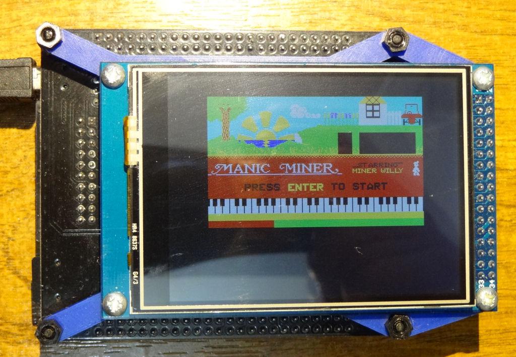 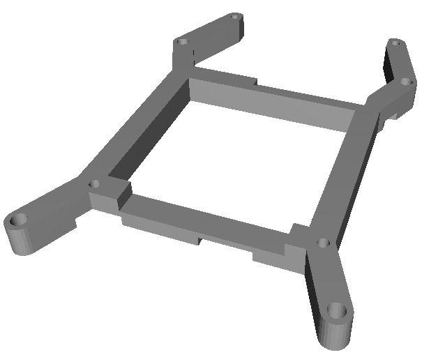 I solder the shim PCB direct to the STM32F4VE 'TFT' pins, and then have a socket (double row of female headers) soldered to the other side for the display module to plug into. ĀThis spaces the display far enough away from the back of the STM board so that the mount is thick enough to allow self-tapping screws to fasten down the display module. 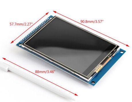 The display has a full-size SD card holder on the back, which you can connect up if you want to - but I don't bother, I use the STM32F4's on-board micro SD. 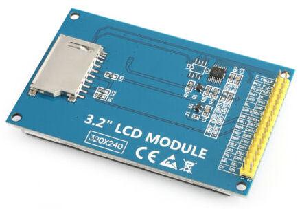 . Edited 2019-10-13 05:38 by ceptimus |
||||
