
|
|
Forum Index : Microcontroller and PC projects : Armmite H7 - Unexpected ADC behaviour
| Author | Message | ||||
| Rodgerg Newbie Joined: 13/10/2019 Location: New ZealandPosts: 12 |
Hello Backshedders While I have been following this forum for some years, this is my first post, so please excuse any formatting errors or unintentional breaches of forum etiquette. Firstly, I greatly appreciate the effort that everyone has put into the 'Mite dynasty over recent years (especially Geoff and Peter) and I have built a number of versions of this trusty helper. In particular, the speed and capacity of the Armmite H7 is amazing and I intend to use it in a Portable Appliance Tester (PAT). However, I have been experiencing some unexpected results from the background ADC routine when using thermmite H7 with matherp's backpack PCB and a 5" LCD display. To explain.... The program below (specifically the ReadV subroutine) samples a 50 Hz waveform at 32 samples per cycle (i.e. 1600 Hz) and prints out the results. SUB InitProg NumSamples = 32 Freq = 50 * NumSamples DIM Volt_Raw!(NumSamples - 1) END SUB SUB ReadV LOCAL i ADC OPEN Freq,34 ADC trigger 1,0.1 ADC START Volt_Raw!() PRINT "Idx";TAB(6);"Volts(Idx)" FOR i = 0 to (NumSamples - 1) PRINT i;TAB(6);STR$(Volt_Raw!(i)) NEXT i ADC CLOSE END SUB I injected the following waveform into Pin 34 on the Armmite H7 (50 Hz sinusoidal, ranging from 0V to close to 3.0V) 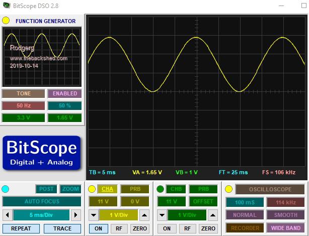 While the background ADC program correctly collects 32 samples, I noticed that adjacent pairs of readings were very similar and this resulted in a strange stepped output when plotted. However, if I plot every second point (meaning only using 16 points), the waveform looks much more as expected. A listing of the program output and the resulting waveforms are shown below. 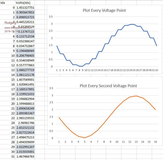 Adjacent pairs have been shaded to demonstrate the issue more clearly. It is almost as if the second result of each pair is taken immediately after the first reading, rather than waiting for the next scheduled time . I have tried two different Nucleo Boards (H743ZI and H743ZI2) and different versions of matherp's firmware (this output was produced by using the firmware file 2019-09-15_191616_Armite1.3), but alas all with the same result. If anyone could point out what I may be doing wrong, that would be greatly appreciated.  |
||||
| matherp Guru Joined: 11/12/2012 Location: United KingdomPosts: 10273 |
Hi Thanks for interesting problem. The firmware does some clever (or perhaps not so clever) stuff to determine the maximum ADC resolution it can use in order to complete the conversion in time for the next one to start. I suspect what is happening is that the algorithm is being too aggressive and sometimes the conversion isn't completing before the next one is due to start. I'll look at this when I get a moment but in the meantime please play with different sampling rates (# samples per 1/20th second). If I am right in my guess as to the cause you may find increasing the sampling rate solves the problem just as well as decreasing it. Please report anything you find. Edited 2019-10-14 20:59 by matherp |
||||
| Rodgerg Newbie Joined: 13/10/2019 Location: New ZealandPosts: 12 |
Hi matherp Thanks for the prompt response and positive suggestion. I will try some different sampling rates when I am back home in a couple of day�s time and post the results. Just from memory, I think I saw the same issue with 16 and 64 samples per cycle (trying to use 2**n to allow for later FFT transformation), but will rerun these checks in controlled conditions to confirm. I will also try some non 2**n options such as 20 and 30 to see if this makes a difference. Stay tuned  Edited 2019-10-15 14:42 by Rodgerg |
||||
| Rodgerg Newbie Joined: 13/10/2019 Location: New ZealandPosts: 12 |
Hi matherp I have now had an opportunity to run a series of tests and have documented the results in the table below. The same grouping effect mentioned in the earlier post is exhibited in a range of sampling frequencies between 400 Hz and 6400 Hz, including a couple of non- 2**n sample rates. Please note that for the 64 and 128 samples per cycle tests, I truncated the list at 32 to save space in the post, but the complete sample was still present in the background. Interestingly, the 8 sample test showed a slight offset in the repetition pattern (as shown), but this was somewhat random when I repeated the 8 sample numerous times. Sometimes it appears on [0,1],[2,3],[4,5...], but at other times it looks similar to the higher order sample rate tests orders [1,2],[3,4],[5,6]�. However, when I ran a large number of 16 sample tests, I did see some variability there too, but the majority of results repeated the pattern highlighted rather than the alternate one. 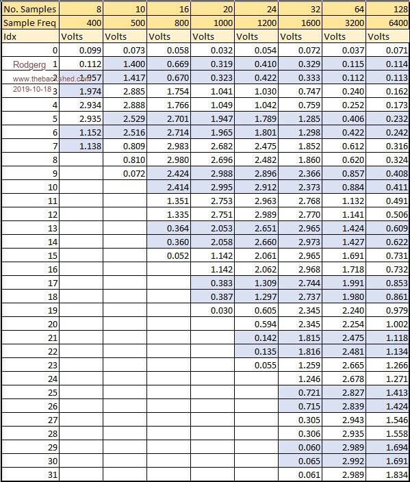 I hope this is helpful and would appreciate any further pointers p.s. The ability to take high speed periodic analogue measurements in the background is extremely useful for mains waveform measurement and does away with any need for a Cfunction. |
||||
| matherp Guru Joined: 11/12/2012 Location: United KingdomPosts: 10273 |
Just one thought before I try and set up a test environment: What is the impedance of your source? It needs to overcome the ADC input capacitance between samples and if too high will give issues. |
||||
| Volhout Guru Joined: 05/03/2018 Location: NetherlandsPosts: 5072 |
Dear Rodberg, In case the sampling frequency of the ADC is from a programmable divider, certain divisors may give duty cycles that are not equal to 50%. To check this, try taking 100 samples at 50Hz (not 64 not 128). About the impedance: the input sampling cap will be charged from the input voltage. If that is a high impedance divider, charging may have delay (latency). Not sure how this would result in a behavior like this, but it will cause artefacts. You may be able to check if this is the case by adding a capacitor (i.e. 1000pF) between the ADC pin and ground (0V). Larger capacitors will be better (i.e. 10000pF) but may attenuate the 50Hz. Succes, Volhout PicomiteVGA PETSCII ROBOTS |
||||
| matherp Guru Joined: 11/12/2012 Location: United KingdomPosts: 10273 |
I've been able to replicate and there is a bug - but at the moment I don't understand the cause. I'll keep working on it but a workaround is to double the frequency and use every second sample. |
||||
| matherp Guru Joined: 11/12/2012 Location: United KingdomPosts: 10273 |
I think I've solved it - please try the attached. I've tested between 2 and 1024 samples per 20mSec. ArmmiteH7.zip My test code - connect pin 34 to pin 40 initProg readv End ' Sub InitProg NumSamples = 32 Freq = 50 * NumSamples Print "Frequency is ",freq,"Hz" Dim Volt_Raw!(NumSamples - 1) ' 'create a sine wave with 4 times the frequency of the ADC sampling frequency 'this ensures the value will move between samples under all circumstances ' Dim d%(NumSamples*4-1) For i=0 To (Numsamples*4-1) d%(i)=2048+1800*Sin(Rad(i*360/(Numsamples*4))) Next i DAC start freq*4,d%(),d%() End Sub ' Sub ReadV Local i ADC OPEN Freq,34 ADC trigger 1,0.3 ADC START Volt_Raw!() Print "Idx";Tab(8);"Volts(Idx)";Tab(24);"Delta" For i = 1 To (NumSamples - 1) � Print i;Tab(8);Str$(Volt_Raw!(i-1));Tab(24);Str$(Volt_Raw!(i)-Volt_Raw!(i-1)) Next i � Print i;Tab(8);Str$(Volt_Raw!(i-1)) ADC CLOSE End Sub Edited 2019-10-19 18:10 by matherp |
||||
| Rodgerg Newbie Joined: 13/10/2019 Location: New ZealandPosts: 12 |
Hi Matherp Yes, it seems that this bug has been successfully "squashed". I have done a run with 32 samples and everything is looking good so far  I will do more testing later today to be sure. I will do more testing later today to be sure.Thanks heaps for taking the time and effort to track this issue down and resolve it. |
||||
| Rodgerg Newbie Joined: 13/10/2019 Location: New ZealandPosts: 12 |
Dear Volhout Thanks for your suggestions. I changed from using a 1M potentiometer to a 1k potentiometer as a potential divider early on thinking this could have been an issue, but it made no difference. It seems that the real problem was an internal bug that matherp has now successfully dealt with. |
||||
| The Back Shed's forum code is written, and hosted, in Australia. | © JAQ Software 2025 |
