Notice. New forum software under development. It's going to miss a few functions and look a bit ugly for a while, but I'm working on it full time now as the old forum was too unstable. Couple days, all good. If you notice any issues, please contact me.
poida Guru Joined: 02/02/2017 Location: AustraliaPosts: 1464
Posted: 11:26pm 19 Dec 2019
Copy link to clipboard
Print this post
I'm not sure this is of interest to many here but anyway..
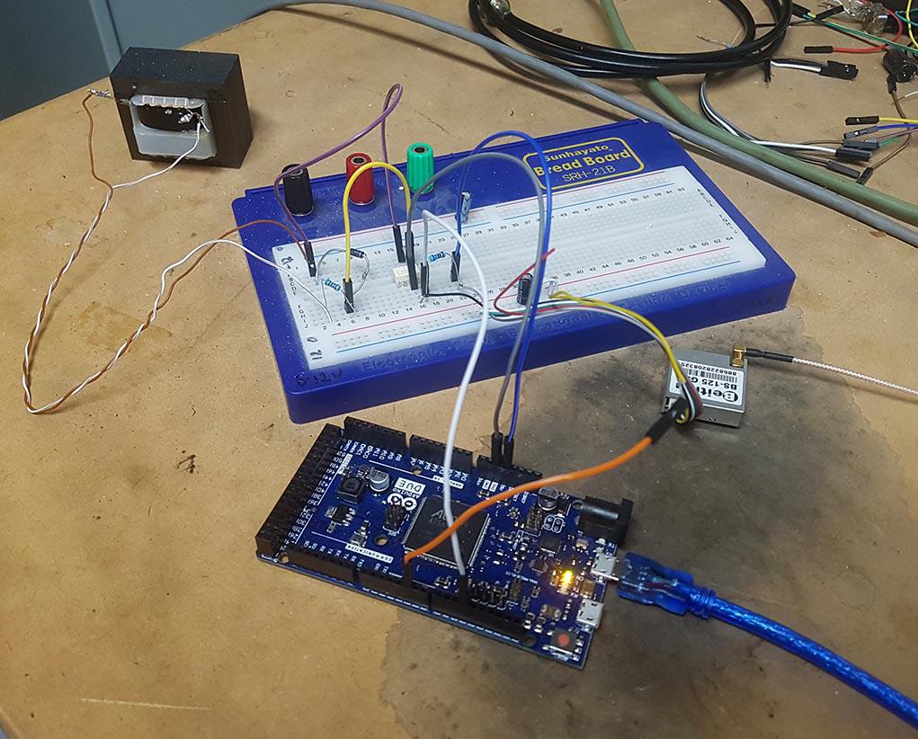
I've developed a device that can measure the frequency of the mains supply to a high standard of accuracy. And it uses a traceable timing standard from a GPS module's 1 pulse per second.
A few specifications:
Accuracy - 7 digits +/- 3 counts (eg 49.99875 +/- 3) Stability - as good as the GPS time system
The electronics are dead easy. Take 12 AC from a transformer, current limit and rectify it, feed it into an opto coupler and take this output into a uC interrupt pin.
That gives us the nominal 50Hz input. Get a $15 GPS module with 1PPS output, power it from the uC (in this case an Arduino Due) and feed it into another pin.
The code has a few functions. Firstly, it runs a locally generated 1 pulse per second timer. This timer is compared with the GPS 1PPS and the local timer period is adjusted to bring it into phase and frequency lock each second. Lock is achieved from cold boot within about 30 seconds, if the GPS has 3 or more satellites visible. Once phase lock is achieved, the adjustments made to the local 1PPS timer are only +/- 2 count. The 42MHz timer clock means we have short term timing changes of the order of 2 parts in 42 million.
So now we have a quite stable 1 PPS local timer, that is kept in phase lock to the GPS 1PPS source. In testing I have seen the GPS module stop emitting the 1PPS due to not enough satellites. The code will continue with the latest correction factor applied to the local 1PPS and keep measuring the mains freq. Short term drift in this case is about 1 part per million per minute of no GPS signal.
I determine mains frequency in a manner that is not obvious. What I do is measure the timing of a rising edge of the 50Hz mains and compare it to the rising edge of the local 1PPS timer. I take the difference of these 2 times, in (timer) clock cycles. (and adjust the calculations to account for the non-exact timer clock rate, which is now disciplined by the GPS 1PPS) This represents the phase angle difference of the mains with respect to the local timer's 1PPS.
If there is no change in phase over time, then the 50 Hz is 50.00000Hz If the phase is changing with respect to time, it results in a mains frequency of 50 - or + the rate of change in phase.
I find this to be extremely accurate and it rejects a lot of noise too. It averages 50 mains cycles and obtains the frequency for those 50 cycles.
Obtaining frequency in this manner is great for a small range, 49.6 to 50.4 Hz It fails when the frequency is outside this tight limit.
The code also determines mains frequency in the "normal" way, by counting timer clocks per rising edge of the mains. This yields a useful measure but it has a good bit of noise in it. But it's useful too, I use it to determine if I can use the delta phase as the source for frequency or not (if it's within that range). If not, just use the clock counting method, which never fails.
The phase lock is so good, I can see the effect of placing a finger on the uC oscillator for a second or two. You will see the phase lock error output change accordingly, as it attempts to maintain lock. I've even seen the effect of blowing on it. The lock error rises about 5 clocks then drops back slowly. The uC seems to use a crystal with a large tempco.
wronger than a phone book full of wrong phone numbers
SimpleSafeName Guru Joined: 28/07/2019 Location: United StatesPosts: 351
Posted: 02:52am 20 Dec 2019
Copy link to clipboard
Print this post
Very nice. :)
CaptainBoing Guru Joined: 07/09/2016 Location: United KingdomPosts: 2171
Posted: 07:02am 20 Dec 2019
Copy link to clipboard
Print this post
Nice project and a lot of fun I bet.
Precise time measurement is a fascination of mine and I have, over the years, played with all sorts of crystal based oscillators with temperature stabilization etc.
I made a frequency meter a few years back which produces an accurate (10 parts in a billion) 1 second gate Āby the traditional method of reducing down through (lots) of counters. It does the job well and I have used it a lot on my bench. With the PC (or at least a serial) connection it can be left to log continuously and and the actual processing is nicely asynchronous to the hardware solution of counting during the gate. Actually, that was a massive leap in accuracy - doing the crucial bit with hardware and reducing the processing side of things to a "supervisory" role. In truth, it was all a bit of a mind game - I have no real reason to want to measure 70MHz (or 700MHz with the prescaler in - but accuracy suffers) to 7 counts - purely a symptom of my madness. I have always disliked not knowing the truth of a matter and inaccurate bench equipment just panders to that for me
I have slowly been driven mad over the years since, as a young lad, coming to the realization that everything... *EVERYTHING* is only ever an approximation so your project is of particular interest in my quest to eliminate error as much as possible. In a thousand years, some archaeologists will stumble across my bleached bones which will still be sporting a furrowed brow. Ā
Keep us in the loop as this develops. Edited 2019-12-20 17:33 by CaptainBoing