Notice. New forum software under development. It's going to miss a few functions and look a bit ugly for a while, but I'm working on it full time now as the old forum was too unstable. Couple days, all good. If you notice any issues, please contact me.
GoodToGo! Senior Member Joined: 23/04/2017 Location: AustraliaPosts: 188
Posted: 10:44am 27 Dec 2019
Copy link to clipboard
Print this post
Howdy all, and I hope you are all having a great festive season!
Anyway, one of my christmas light crappy multi-function controllers shat itself. So enter an Explore 28 module! I designed a quick circuit and roughed up some code to imitate some of the routines the crappy 3-wire multi function controller used to do:-
Works great and is happily driving the 3-wire LED strings on my fence. However I would like to drive another set of 3-wire strings using the other PWM channel in the MM as well. But having the channels run different routines at the same time. e.g. the first 3-wire string on PWM channel 2a/b running, say, the slowfade routine, while the PWM channel 1a/b is running the chase routine. Is this at all possible? Do I have to timeslice somehow?
Cheers,
GTG! ...... Don't worry mate, it'll be GoodToGo!
bigmik Guru Joined: 20/06/2011 Location: AustraliaPosts: 2980
Posted: 12:48am 28 Dec 2019
Copy link to clipboard
Print this post
Hi GTG,
Any video clip of it working.
I have a retiring reindeer that I want to re-jig for next years Christmas either with discrete LEDs or simply the LEDs with inbuilt colour change flashing cct.
PeterB Guru Joined: 05/02/2015 Location: AustraliaPosts: 667
Posted: 02:12am 29 Dec 2019
Copy link to clipboard
Print this post
G'Day GTG
I know this will get me shot down but. Most of the time your MM is doing nothing, pause x, so can you take advantage of that.
Good luck
Peter
Turbo46 Guru Joined: 24/12/2017 Location: AustraliaPosts: 1685
Posted: 03:08am 29 Dec 2019
Copy link to clipboard
Print this post
As PeterB said, there is a lot of PAUSEing in the program. Maybe it could be re-written to use timer interrupts? The thought of it makes me shudder. I would just use another Micromite.
Thanks for sharing the code though. I'd love to see a schematic of the hardware too.
BillKeep safe. Live long and prosper.
PeterB Guru Joined: 05/02/2015 Location: AustraliaPosts: 667
Posted: 03:26am 29 Dec 2019
Copy link to clipboard
Print this post
Now I am sticking my neck out
If you time slice into 10ms blocks you should be able to do quite a lot in a block and it should look good.
Peter
GoodToGo! Senior Member Joined: 23/04/2017 Location: AustraliaPosts: 188
Posted: 10:17am 29 Dec 2019
Copy link to clipboard
Print this post
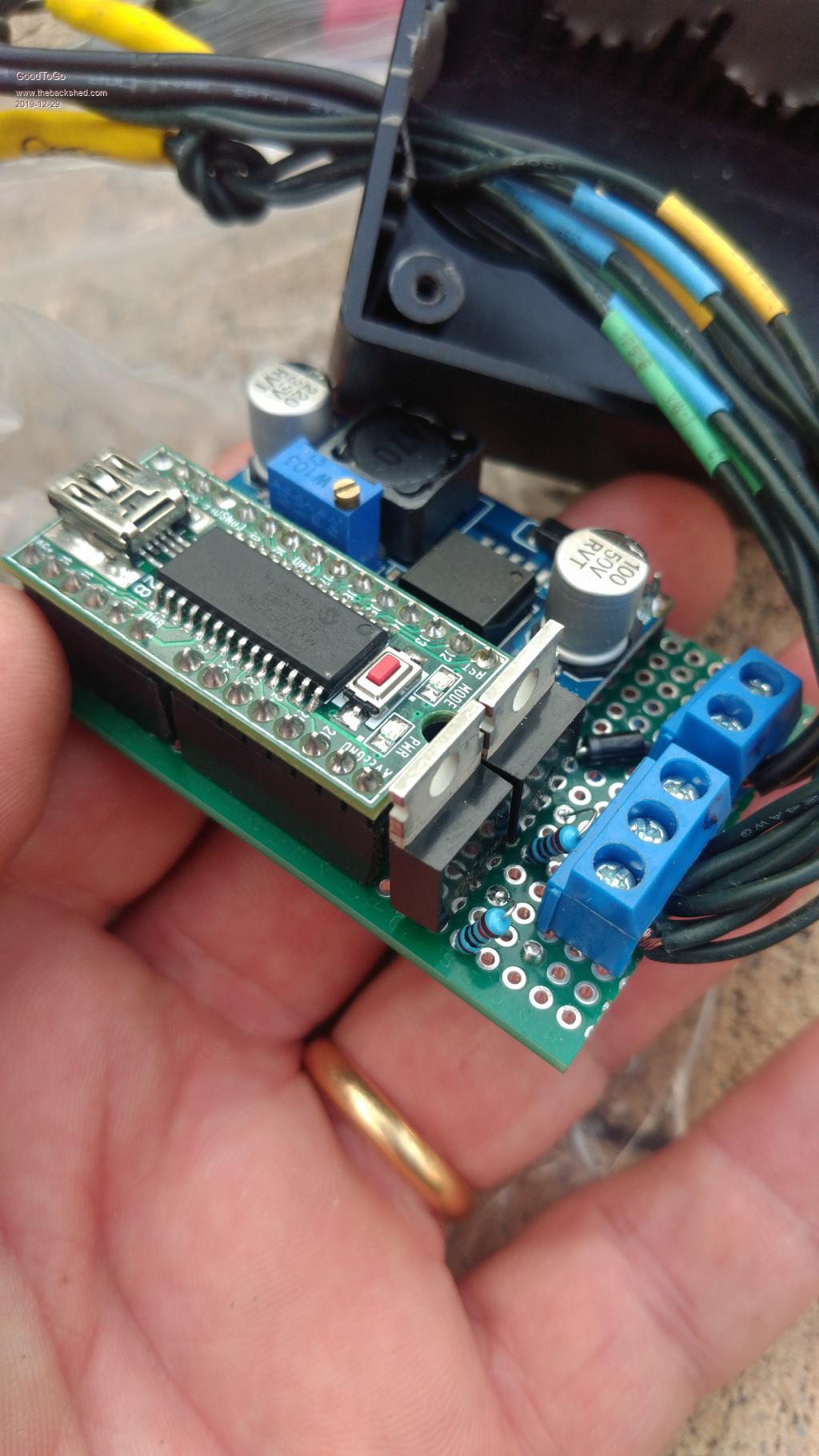
Howdy all, a couple of pictures and a schematic for you all:-
As you can see, there's not much to it. An ebay-special buck converter drops the incoming 32Vdc down to 5Vdc for the E28 module. The 32Vdc then just goes to the connector for the LED string. The two negative sides on the strings are driven by 2 logic level N-channel IRL540N MOSFET's, whose Gates are connected to pins 24 & 26 of the E28. A 10K resistor connects each Gate to ground. BigMik, I'll try to get some video footage for you......
Cheers,
GTG! ...... Don't worry mate, it'll be GoodToGo!
GoodToGo! Senior Member Joined: 23/04/2017 Location: AustraliaPosts: 188
Posted: 11:14am 29 Dec 2019
Copy link to clipboard
Print this post
Uploaded a video clip here. Forgive the blurriness of it, the phone had trouble focusing....
Cheers,
GTG! ...... Don't worry mate, it'll be GoodToGo!
bigmik Guru Joined: 20/06/2011 Location: AustraliaPosts: 2980
Posted: 01:23am 01 Jan 2020
Copy link to clipboard
Print this post
Hi GTG,
I like it..
Dismantling our Christmas tree (sits out the front) I noticed a similar circuit driving the LEDs from 31Vdc... If the controller ever dies I will steal your idea.. In fact I think your display looks better than the original ... well at least in my case.