
|
|
Forum Index : Microcontroller and PC projects : Saving battery with Micromite and Display
| Page 1 of 2 |
|||||
| Author | Message | ||||
OA47 Guru Joined: 11/04/2012 Location: AustraliaPosts: 1048 |
The needs of a Micromite program has led me to find a way to preserve battery drain on a handheld project. I wanted to be able turn on the unit easily and be able to turn it off by software (like a multimeter) after a pre determined time or when I have finished testing. I have devised a simple MOSFET circuit that will operate the Micromite and display when a momentary button is held in long enough for the Micromite software to push high an I/O pin to hold the mosfet on. Once the unit is running I used a Touch button to remove the output of the I/O pin or set a timer that will also turn off the unit if there is no input to the program for some duration. The circuit draws about 15uA when not in use which is quite acceptable for my needs but there maybe some tweaking that could reduce this further if needed. Maybe someone might find the circuit handy. 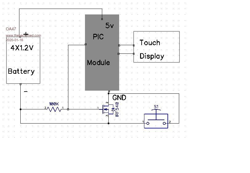 |
||||
| Turbo46 Guru Joined: 24/12/2017 Location: AustraliaPosts: 1685 |
That could be useful, thanks. I came up with a similar circuit for a PICAXE: 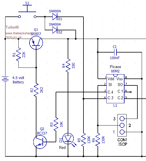 This allows a subsequent push of the pushbutton to extent the timer. You could add a (blinking?) LED (or a beep) to indicate when the timer is nearly up as a prompt to push the button again. I have not kept up with FETs so I used transistors but I realise that a FET would be better. I could not measure any current drain when it was off. Output C4 is raised as the first job of the micro and lowered at the end of the timer to turn the power off. I later found a similar circuit for an Arduino here. Bill Keep safe. Live long and prosper. |
||||
| Volhout Guru Joined: 05/03/2018 Location: NetherlandsPosts: 5859 |
Dear OA47, I am not sure how your circuit works. Does the PIC module contain a open drain P-FET ? When the IRF540 is off, the source is at - level (say 0V), the drain switched off the PIC, so the PIC has 0V across it. This means that the drain of the FET is at +5V. The PIC itself has Vdd=+5V, and since it is switched off, Vss=+5V. How can the PIC output (IO pin) be at 0V level..? Due to internal diodes (inside the chip) the voltage at the IO pin can be between +5.6V and +4.4V, turning the FET on. I have the idea that the PIC is snot switched off completely, it still has some 2V across it (Vdd=+5V, Vss=+3V). The IO pin is at 2.5V, and that is insufficient to turn of the FET hard. So it is leaking 15uA, insufficient for the PIC to start or run. The circuit is a balance between FET choice and PIC choice. Although this could work for you, I would not suggest this for all PIC's and different FET's. Turbo's circuit does not exhibit this problem. Although, for a 08M2, it may not be necessary. There is a demonstration of a picaxe 08M2 that has been running in low power mode (without any surrounding circuit) for 11 years, blinking a LED, on AA cells. That seems low power enough. PicomiteVGA PETSCII ROBOTS |
||||
| CaptainBoing Guru Joined: 07/09/2016 Location: United KingdomPosts: 2171 |
very interesting subject. I have tinkered with this on and off over the years but it was always a solution looking for a problem, I never got to actually use it in anything. My approach was similar to yours OA but I went for a PType in VCC - was afraid of parasitic leaks to GND through other components. seem to remember something like; the gate was held high though a resistor and the switch pulled it low, power then went to the uP which pulled the same line low - sort of like a latching relay circuit (which probably inspired it in the first place). Again, until a timer fired, the line went high and the thing turned itself off. It was a long time ago so I might be a bit hazy on the deets. Might have to start playing again, See what you've done? �  Edited 2020-01-16 22:43 by CaptainBoing |
||||
| Turbo46 Guru Joined: 24/12/2017 Location: AustraliaPosts: 1685 |
I did have plans to expand my circuit to make a remote control. If you duplicate the D!/R5 part of the circuit into another input. Do this several times and you can have several inputs. Push a button, send a code, turn off. Save battery. Probably R5 can be replaced with an internal pull-down. Bill Keep safe. Live long and prosper. |
||||
| OA47 Guru Joined: 11/04/2012 Location: AustraliaPosts: 1048 |
In my situation I am using an Explore 64 module. I think I did put a 1K resistor from PIN 11 to the FET. At the start of the program: SetPin 11, DOUT Pin(11)=1 To manually Power Down: Sub PowerOff I=MsgBox("Ready to power down","POWER OFF") Pause 100 CLS SetPin 11, OFF End Sub I do like to keep things as simple as possible. I had a quantity of these MOSFETs as I used them in a solar regulator circuit that was set up in a similar fashion except the circuit bridged the 10W panel when the limit voltage was achieved. OA47 |
||||
| CaptainBoing Guru Joined: 07/09/2016 Location: United KingdomPosts: 2171 |
hackaday plays with a p-channel mosfet as a hi-side switch https://www.youtube.com/watch?v=flYr9ubKIoQ |
||||
| Turbo46 Guru Joined: 24/12/2017 Location: AustraliaPosts: 1685 |
Thanks for that Captain. I note that he uses the same device as the Random Nerd guy. It looks like it could be plugged into my circuit in place of the BC327 and change R1 to 100k. A bit of research suggest that to IRF540 or IRF9540 are not really suitable because the drain to source voltage needed to turn it on fully is too high. Someone in the know might like to comment? I must get some to play with. Bill Keep safe. Live long and prosper. |
||||
| CaptainBoing Guru Joined: 07/09/2016 Location: United KingdomPosts: 2171 |
you are most welcome. I think it is a very real possibility to switch off things that aren't being used in battery applications. Only thing I would change about your suggestion above is I �would probably drop the 100K to 10K (maybe even lower if it is being switched often) - I know there is no current involved but there will be a charge to bleed on/off the gate. That capacitance through a 100K might make the switching not as sharp as it could be. If we guess that the capacitance on the gate is 5pF, a 100K will give a rise/fall time of 2.5mS (using the 5CR seconds formula) MOSFETS get warm when they are moving in and out of the trans-conductance zone so when using them as a switch, I like to make it as snappy as possible. From an "off" current draw perspective it won't make any difference to standby juice as the gate is insulated (hence the not-inconsiderable capacitance). I am possibly clucking for no reason about it as the FET won't be trans that often, it's not like it is PWM �signal driving a motor or something. Once in a blue moon won't cause any harm. my 2p Edited 2020-01-17 23:04 by CaptainBoing |
||||
| lizby Guru Joined: 17/05/2016 Location: United StatesPosts: 3740 |
IRL540, IRLZ44 (older, cheap "logic level" parts, probably suitable here for low-side switching) or, say, IRLB8743PBF for high speed switching. Edited 2020-01-18 00:48 by lizby PicoMite, Armmite F4, SensorKits, MMBasic Hardware, Games, etc. on FOTS |
||||
| Turbo46 Guru Joined: 24/12/2017 Location: AustraliaPosts: 1685 |
Thank you again Captain. In my case the circuit was not switched very often, it was for a child's music box. But in my experience the turn on time for a micro should be fairly snappy so that it starts up properly. 10K sounds good. Thanks lizby, I'm with Captain on preferring to switch the high side. I like a good solid 0v. And thank you OA47, you've re-kindled my interest in this circuit and I've learnt something. I need to learn more about FETs also. Bill Keep safe. Live long and prosper. |
||||
| CaptainBoing Guru Joined: 07/09/2016 Location: United KingdomPosts: 2171 |
+1 a very enjoyable canter and stretch of the grey matter. One thing I've learned about FETs: I don't know enough about FETs, they are still able to surprise me with how useful they can be. I re-designed an H-bridge driver for a solenoid water valve a few years back, replaced some chunky BJTs (TIP???) and I was able to dispense with the four bypass diodes (for the back-EMF protection) by careful selection of the body diode specs. For the sake of a $0.40 FET and a resistor I really should re-visit my efforts at switching off bits I am not using if I have spare pins available; always had it bouncing around in my head but never actually done it. Thing is for me, battery operated projects are few and far between so when I am drawing power from mains, it just encourages design-sloppiness and a "what does it matter?" attitude (well, in me anyway)... in my defence, it was cheaper and a reduced complexity - that's my excuse anyway The only battery powered thing I really did (professionally/commercially) was the barrel sterilizer probe. It travels with a barrel through the autoclave to certify the conditions to extinguish life and it's active the whole time with pressure/temp readings for the cycle, no real candidates for switching and no driver coz battery power isn't an issue for the relatively brief periods off the juice. Other stuff has just been for me and I always have a stack of freshly charged cells ready so there is no driver to be frugal. See what I mean about sloppy?  Edited 2020-01-18 18:09 by CaptainBoing |
||||
| Andrew_G Guru Joined: 18/10/2016 Location: AustraliaPosts: 874 |
Hi, I'm interested in a simple circuit (simple enough for a Civil Engineer who studied valves at school/uni). Push switch to wake it up and a timer, or Touch, to turn it off (the software I can do). 1) Could "someone" possibly distill the above discussion to produce an updated circuit for a MM2/LCD Backpack?? 2) How best to turn power off to the LCD display whilst leaving the MM running for other tasks? (it would be a subsequent press of a switch to turn off the MM). Many thanks, Andrew (I currently use a battery pack for 5V for an infrequently used project - self contained batteries would be great) |
||||
| Turbo46 Guru Joined: 24/12/2017 Location: AustraliaPosts: 1685 |
I could design a circuit to do that, it would be a combination of my circuit above and the Random Nerd's. Not sure whether I should: 1. because this is not my post and 2. it will be a week or so before my NDP6020Ps arrive and I can test it. I think you will have to do some surgery on the backpack board to enable turning off the LCD though. You could use one push to turn the whole thing on, another to turn off the LCD, then another to turn on the LCD... A long push (or timer) to turn the whole thing off. Bill Keep safe. Live long and prosper. |
||||
| CaptainBoing Guru Joined: 07/09/2016 Location: United KingdomPosts: 2171 |
|
||||
| CaptainBoing Guru Joined: 07/09/2016 Location: United KingdomPosts: 2171 |
it's all learning Bill. I have seen (and been part of) much more rambly posts. Speak your brains!  h |
||||
| Volhout Guru Joined: 05/03/2018 Location: NetherlandsPosts: 5859 |
Hi OA47, I am happy to design a circuit for you, if you want. Please specifiy what your input voltage (and range) is. Specify what you want to keep running in low power mode. Specify what you want to switch off in low power mode. Note that you sometimes can make your life simpler by looking at voltage regulators (5V -> 3.3V) with an enable pin... Some even have "ON-OFF" logic inside them specific for this application, including switch debounce. Regards, Volhout PicomiteVGA PETSCII ROBOTS |
||||
| Turbo46 Guru Joined: 24/12/2017 Location: AustraliaPosts: 1685 |
Andrew, Here is my version of the circuit. My NDP6020Ps are still coming via snail mail so I haven't tried it yet. Bearing in mind CaptainBoing's comments above, a TO220 FET capable of passing 20 Amps may be overkill but it should be pretty robust. Also I left the gate resistor at 100K so if there is any suspicion that the circuit does not start up reliably this could be changed to 10K with no problems. Just a bit more current drawn while on. I just looked at that Youtube video and the resistor used there appears to be 4K7. Pushing the switch will turn on Q2 via D2 and R2 which will ground the gate of Q1 and turn it on. The first thing the Micro should do is raise the output to logic '1' to hold Q2 on. Set it low to turn the power off. The Micro input can detect subsequent pushes of the switch via D1 and R5. The resistor from the base of Q2 to 0v is necessary to ensure the transistor is fully turned off when there is no input because the diodes D1 and D3 prevent the input signals connecting the base to ground. 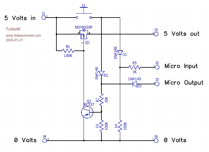 The circuit to control other devices is below. 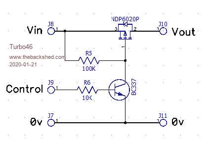 The transistor could be any small signal NPN transistor you have available. Bill Keep safe. Live long and prosper. |
||||
| lizby Guru Joined: 17/05/2016 Location: United StatesPosts: 3740 |
What is the function of R1? PicoMite, Armmite F4, SensorKits, MMBasic Hardware, Games, etc. on FOTS |
||||
| Turbo46 Guru Joined: 24/12/2017 Location: AustraliaPosts: 1685 |
R1 keeps the Vgs (Gate to Source voltage) below the Gate Threshold Voltage while Q2 is off. For a static (on or off) condition there is no current drawn, so a high value is fine. Minimum gate threshold is -0.4 volts according the the datasheet. During switching, the Gate to Source capacitance must be charged or discharged and current is drawn through R1 to do this. With a lower value of R1 the Gate voltage will fall more quickly and so the FET will turn on more quickly giving a faster output voltage rise time. We are only switching milliamps so the gate voltage does not have to fall very far to fully turn the FET on so I believe the rise time will be OK. Please see CaptainBoing's comments above. @ CaptainBoing, as I said above, I have not kept up with FETs and did not even consider the effect of gate capacitance. Do you have any comments on the above. Bill Keep safe. Live long and prosper. |
||||
| Page 1 of 2 |
|||||
| The Back Shed's forum code is written, and hosted, in Australia. | © JAQ Software 2026 |
