
|
|
Forum Index : Microcontroller and PC projects : Saving battery with Micromite and Display
| Author | Message | ||||
| CaptainBoing Guru Joined: 07/09/2016 Location: United KingdomPosts: 2170 |
Think of R1 as a pullup to stop the gate floating while there is no influence from the PIC (via Q2). FETS have such high impedance (sometimes even a few Giga-ohms) between their gates and the rest of the inner workings that this presents as a tiny capacitance and they can and do act like a memory (single-transistor-cell DRAMS are actually manufactured to exploit this feature). You can connect it to a voltage which will put a charge on the gate - disconnect the gate (i.e. leave it floating) and the charge will just sit on the gate for quite a while. I had a vid that I can't find right now where I have an LED driver built from FETs and I demonstrate the latching nature by touching a positive wire to the gate to turn it on - the FETs stayed on when I removed the wire and I had to touch a ground wire to the gate to turn it off again. With the gate just floating like that, sometimes the LEDs would slowly start to glow building up to quite a brightness as charge from the surroundings accumulated and turned the driver FET on - with nothing connected to the gate... spooky. This is what R1 is preventing above. Incidentally (and this is a very rough generalization with lots of room for improvement), this is why MOS stuff is so easily damaged by static charge. Consider that it might take 4KV or so to stick a balloon to the wall but that charge it just sitting there - it has no current, no flow - hence static. As soon as you start to draw power from it (which has a current component, W=V*I) the voltage drops incredibly rapidly to almost nothing (simple power conversion). This is why a "Normal transistor" (BJT), say a BC107, which is current controlled, is not so vulnerable to static - as soon as there is a charge, it starts to conduct, draw current and in a few microseconds or less, the voltage has dropped away to nothing and it isn't exposed to the very high voltage for much more than nanoseconds. A MOS device on the other hand draws no current (ish) and so the voltage stays at "4KV"... not many small components are gonna like that. In this circuit, as far as the gate capacitance is concerned; I think the activation/deactivation is so infrequent that for the current being drawn through the MOSFET you can forget the "slow" rise time... so long as the PIC wakes up OK. If it doesn't, your suspicions should definitely fall on that resistor and you should progressively halve it until it does, but no less than 4K7. If it is still mucking about at that level, change it back to 10K and look elsewhere. hth h |
||||
| lizby Guru Joined: 17/05/2016 Location: United StatesPosts: 3358 |
Thanks--I hadn't been able to orient my way of looking at it correctly. PicoMite, Armmite F4, SensorKits, MMBasic Hardware, Games, etc. on fruitoftheshed |
||||
| CaptainBoing Guru Joined: 07/09/2016 Location: United KingdomPosts: 2170 |
Hello Turbo. I am curious, why the "helper" transistor Q2? what is wrong with... 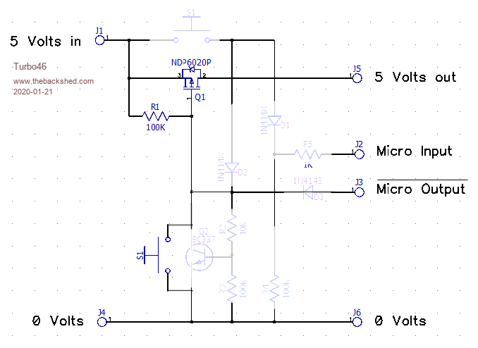 I must have missed something �  Edited 2020-01-22 07:38 by CaptainBoing |
||||
| Andrew_G Guru Joined: 18/10/2016 Location: AustraliaPosts: 871 |
Many thanks to you all. I think I do understand (thanks to your explanations and discussion too). As I understand it: - the main circuit manages how the MM performs - also, multiple separate control circuits could be used to turn off/on other devices (with relatively low current draw) by connecting each's Vout to their respective device's Vcc (such as LCD screens, HC-12 etc). Each controlled by a MM pin. Very useful. Regards, Andrew |
||||
TassyJim Guru Joined: 07/08/2011 Location: AustraliaPosts: 6269 |
"I am curious, why the "helper" transistor Q2?" The microprocessor pins have diodes to the supply rail. This might pull the output low when power is removed and this in turn will turn the FET on. The helper transistor removes that problem. Jim VK7JH MMedit |
||||
| Turbo46 Guru Joined: 24/12/2017 Location: AustraliaPosts: 1639 |
Also remember that the Micromite is running from 3.3 volts so a logic '1' will not turn off the FET. In my case I wanted to detect subsequent operations of the switch so I had to provide for that. With a little modification the circuit could be self latching (ie not need the micro output to latch) but turning it off would require extra components. Andrew, TassyJim's dual function push button code may be of interest. CaptainBoing, thank you for the description above. Bill Keep safe. Live long and prosper. |
||||
| CaptainBoing Guru Joined: 07/09/2016 Location: United KingdomPosts: 2170 |
@TassyJim @Turbo46 see? told you I missed something. In my defence... it was getting late after a trying day �  Seriously, thanks for clearing that up - also explains why Q2 has to be a BJT. Seriously, thanks for clearing that up - also explains why Q2 has to be a BJT.As my (probably) last word on all this, I found these two excellent vids which really explain two things in detail: 1. the power losses when switching and that weird curve as trans-conductance kicks in �here 2. the capacitance effects of the gate - I must say I was really surprised by how high it was on some examples - several hundred pF and this would definitely have an impact of a high value of pullup (illustrated really well in the vid). here One really good point that came out from the comments was to always (try to) drive the gate at a voltage at least twice Vgs to get the FET to switch on early in the charge curve if you can. enjoy. Edited 2020-01-22 18:22 by CaptainBoing |
||||
| CaptainBoing Guru Joined: 07/09/2016 Location: United KingdomPosts: 2170 |
LOL, Lewis Loflin agrees. He threw his in the bin https://youtu.be/E-RgV2bw5_k?t=273 On another tac, there is also using an N-channel device as a high-side switch with bootstrapping... https://www.youtube.com/results?search_query=high+side+bootstrap but I'm saying nothing. Edited 2020-01-23 00:21 by CaptainBoing |
||||
OA47 Guru Joined: 11/04/2012 Location: AustraliaPosts: 982 |
Looking at the discussion that has followed my original post it seems that I got lucky with my simple arrangement as the 3.3V out of the PIC shouldn't be enough to hold on the IRF540N FET gate. I have tested the circuit many times over the past week and it still behaves as I intended. If I get time I might change out the FET and see if others are perform the same. OA47 |
||||
| Turbo46 Guru Joined: 24/12/2017 Location: AustraliaPosts: 1639 |
From what I understand of the specs for the IRF540N it needs 4.5v from gate to source to switch 10 Amps there is no information for voltages and currents below that. Maybe it is quite capable of switch 200mA at 3.3v gate to source? I guess the 15uA you measure while off is the leakage via the 100K resistor through the micro's I/O pin. I also guess that your circuit would work with an NDP6020P in the positive supply. Bill Keep safe. Live long and prosper. |
||||
| Pluto Guru Joined: 09/06/2017 Location: FinlandPosts: 375 |
With NDP6020P it should be OK to switch down to 4V supply. I made some tests with FQP27P06 (P-MOS, 60V, 27A, 0.07 ohm). It seems to be possible with this one to also switch 3.3V (and 2.5V). FQP27P06 from AliExpress USD 0:20 each.  |
||||
| Turbo46 Guru Joined: 24/12/2017 Location: AustraliaPosts: 1639 |
Well I built my circuit using the NDP6020P and it works as expected. I can measure no current when it is off. Driving a 170 backpack there is about 0.1 volts across the FET. I connected an extra 22R resistor (approx 220mA load) and a 100uF capacitor across the load after the FET and the circuit operated correctly as before with about 0.3 volts across the FET. I was worried about the gate capacitance as mentioned by CaptainBoing - see here for a further explanation, but I realised that the FET is not being turned on via the 100K gate resistor but by the transistor so the gate capacitance should not be an issue with turn on. I noticed that the Micromite takes a little while to start up and start running the program so the switch must be held on for a half second or so to ensure the FET is latched on. I could not find a suitable TO92 FET for the job but Silicon Chip have used an IRF9333 FET in their Explore 100 and other designs as an protection against input supply reversal. It is a surface mount device and I am sure it would be quite suitable. Bill Keep safe. Live long and prosper. |
||||
| CaptainBoing Guru Joined: 07/09/2016 Location: United KingdomPosts: 2170 |
Thanks for the update Bill. I am really pleased everything is working as planned. Is the MM startup noticeably longer than when it was powered directly? half a second I think is acceptable for boot with the LCD etc., no? This was the reason behind me suggesting an "alive" LED so you can simply hold the button until the light comes on. Setting the gate-pin on should be absolutely the first thing your code does but when LCD panels are defined I am guessing there is a lot of house-keeping MMBasic does while booting, i.e. before it hands control to your code. How does it perform when it turns itself off? Should be instant. good work � As an aside, it only occurred to me some time after this thread petered out, you could do the same with a Thyristor (SCR), the turn on would be a switch to the gate, there is no need to hold the SCR on and a transistor across the thing to short it out act as your turn-off. 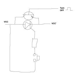 Not a recommendation (I still think the FET is best due to power dissipation ~0) just an alternative... SCRs don't get used enough � The advantage with the SCR is the turn on is instant as you don't need the microcontroller to assert a pin to "take over" from the switch. The uC only turns itself off by shorting out the SCR, ICC is then transferred to the CE path in the transistor (which could be a N-FET) and then when the base drops away the thing goes off.Edited 2020-02-07 23:21 by CaptainBoing |
||||
| Turbo46 Guru Joined: 24/12/2017 Location: AustraliaPosts: 1639 |
I guess that some of the delay is due to the internal 3.3 volt supply stabilising and MMBASIC tokenising commands etc. I'm using the backpack V1 with a pot setting the screen backlight. The backlight comes on immediately the button is pushed so power is supplied when then the button is pushed as you would expect. Turn off is instant - to the naked eye anyway. I think your SCR idea is a good one although an NPN transistor would need a voltage higher than the input voltage to turn it on. A PNP transistor or the NDP6020P MOSFET could do the job though. I think an SCR has a higher voltage drop but that may not be a problem. Providing an input to detect a subsequent push of the button may be difficult too. I have to investigate further, Thank you Captain, this is why I love this forum. Bill Keep safe. Live long and prosper. |
||||
| CaptainBoing Guru Joined: 07/09/2016 Location: United KingdomPosts: 2170 |
OK, that nails it really, the half second is the micromite booting yeah it was an un-researched scribble just to capture the idea. You are correct of course. Edited 2020-02-08 00:48 by CaptainBoing |
||||
| Turbo46 Guru Joined: 24/12/2017 Location: AustraliaPosts: 1639 |
I forgot to mention, there is a little gotcha! in my circuit above, and for the original one using a Picaxe. To download a new program you MUST short out the switch (or hold it on) because the act of downloading a new program will turn off the transistor and therefore the supply to the micro and the download will fail. Bill Keep safe. Live long and prosper. |
||||
| The Back Shed's forum code is written, and hosted, in Australia. | © JAQ Software 2025 |
