Home
JAQForum Ver 24.01
Log In or Join  
Active Topics
Local Time 01:58 02 Jul 2025 Privacy Policy
Jump to

Notice. New forum software under development. It's going to miss a few functions and look a bit ugly for a while, but I'm working on it full time now as the old forum was too unstable. Couple days, all good. If you notice any issues, please contact me.

Forum Index : Microcontroller and PC projects : Graphics, BMP support and GIF images.

Author Message
MustardMan

Senior Member

Joined: 30/08/2019
Location: Australia
Posts: 175
Posted: 07:31am 17 Apr 2020
Copy link to clipboard 
Print this post

Hi,

I am implementing a front-end for an industrial controller, and users expect touch screens with nice graphics these days, so I am using an SSD1963 7" TFT display (800x480) but am having serious speed issues displaying graphics.

Loading a BMP from an SD card takes a terribly long time in relation to what users expect - the fastest I have been able to load a full screen is just over a second. Users these days expect pages to just instantly appear.

Dealing with the splash screen is pretty easy, I just turn the backlight off, load the image, and turn it on again. Image instantly appears. However, when running the main loop I have no such luxury.

I had thought I was saved for about an hour, reading in the "Micromite Plus Manual, MMBasic Ver 5.05" on page 22 ... "All types of the BMP format are supported including black and white and colour 24-bit images" ... If I could load a reduced pixel depth image, and then RLE compress it as well, getting the data off the SD card would be much faster (I assume the main bottleneck is the SPI/SD card interface).

However, after running some tests, indexed colour images are not supported, and neither is RLE compression (both are part of the official BMP specification). So the statement "All types of BMP format are supported..." is clearly false. Perhaps the statement was meant to be "Only black and white and 24-bit BMP image types are supported"??

I can't use a BLIT because the PIC memory is simply too small for the whole screen (BLIT uses 3 bytes per pixel) otherwise I would/could pre-load the BLIT memory and dump that to the screen to change pages.

I should note that my main page could be represented by 256 colours very easily, and I could probably get away with 16 (it is a diagrammatic representation of the system).

Has anybody considered implementing proper (full) support for BMP images, or implementing support for (single plane) GIF images?

Also, or alternatively, does anyone have any ideas on how I could speed up page changes - less than .2 seconds would be nice, less than .1 seconds would be fantastic. The time between page changes is measured in tens of seconds.

Cheers, Mustard.
 
SimpleSafeName

Guru

Joined: 28/07/2019
Location: United States
Posts: 351
Posted: 07:46am 17 Apr 2020
Copy link to clipboard 
Print this post

Probably not much help, but out of curiosity, what industrial controller are you using?

For this kind of thing I use AdvancedHMI. It's free, it comes with the source, and you can use it on a Raspberry Pi (through Mono) and it's a mature product. It's designed for PLCs, but it should be able to connect to anything that talks Modbus.
 
MustardMan

Senior Member

Joined: 30/08/2019
Location: Australia
Posts: 175
Posted: 10:04am 17 Apr 2020
Copy link to clipboard 
Print this post

@SimpleSafeName

The industrial controller is a custom built device. Very early PIC 32 micro. Half a dozen inputs, half a dozen outputs, both inputs and outputs are a mix of analog, digital, PWM, current loop, 0-10 volt, and more. It is an excellent unit although now quite old. The idea is to give the thing a cosmetic face lift so it looks spunky on top, but underneath it runs exactly the same algorithms and does exactly the same thing. Where this controller is deployed reliability is mandatory, something as simple as a slight slip up in the PID loop parameters could cost tens or hundreds of thousands.
 
lizby
Guru

Joined: 17/05/2016
Location: United States
Posts: 3348
Posted: 12:17pm 17 Apr 2020
Copy link to clipboard 
Print this post

Have you seen Tinine's posts on android as HMI industrial controller device for micros, especially micromites?

"Android devices make awesome HMIs for MCUs"
https://www.thebackshed.com/forum/ViewTopic.php?TID=11950&PID=143748#143748

And other posts. Search on Android with Tinine as author. He seems to have developed an excellent hardened industrial-grade solution.
Edited 2020-04-17 22:21 by lizby
PicoMite, Armmite F4, SensorKits, MMBasic Hardware, Games, etc. on fruitoftheshed
 
panky

Guru

Joined: 02/10/2012
Location: Australia
Posts: 1114
Posted: 12:29pm 17 Apr 2020
Copy link to clipboard 
Print this post

Rather than load .bmp image diagrams, you might consider creating one or more custom fonts to make up elements of your system (valves, solonoids, motors, cutters etc. and interconnecting workflow lines etc.)

By using the page swap features of MMBasic, you could jump through different diagrams virtually instantly. Tassyjim's Fonttweak program can be used to build custom icons (equating to letters of the alphabet) that can be placed anywhere on the screen(s).

You could even animate these reasonably simply. For example to indicate a fault in a particular function, just change the font colour (to red for instance) of a failed motion?.

To manipulate multiple .bmp images on and off an SD card, IMHO, is not a really practical way to display different diagrams as the time taken is a function of the read/write speed of the SD card as well as MMBasic.

Just a few thoughts - I wish you well with your project.
panky
... almost all of the Maximites, the MicromMites, the MM Extremes, the ArmMites, the PicoMite and loving it!
 
Volhout
Guru

Joined: 05/03/2018
Location: Netherlands
Posts: 5023
Posted: 12:30pm 17 Apr 2020
Copy link to clipboard 
Print this post

Hi MustardMan,

The ArmmiteH7 is the fastest mite that can drive an SSD1963 LCD.
It is significantly faster than the MM+. You did not specify what you where using ATM, but I assume an MM+.

If the H7 is not fast enough, you will have to revert to Raspberry Pi's.

Do not go down the path using Picromite (MMbasic on Raspberry Pi), it is slower than  the ArmmiteH7 (probably due to Linux overhead) and has a longer startup time (not handy for a man-machine interface .. the machine is already running, but you can't see yet what it is doing).

Volhout

If you need a blistering fast OS on the Raspberry Pi that you can program in basic, look at RiscOS. It has embedded BBC-basic V. Boots in 3 seconds on a Pi Zero. Does not run on a Pi4. Has a learning curve however.. (a lot skills we acquired over the years with mouse and keyboard work really different....).
Edited 2020-04-17 22:31 by Volhout
PicomiteVGA PETSCII ROBOTS
 
MustardMan

Senior Member

Joined: 30/08/2019
Location: Australia
Posts: 175
Posted: 01:06am 18 Apr 2020
Copy link to clipboard 
Print this post

@Volhout
I am currently using an Explore 100.

@panky
I am starting to think that something along those lines may be the solution. So far the non-primitive (eg: other than line, circle, etc) graphics commands that may help me are:

BLIT : 24bpp colour. Needs a graphic to copy. Speed?
SPRITE : Probably colour? Fixed XY size? Bit depth? Speed?
GUI BITMAP : Monochrome?
FONT : 1bpp monochrome (foreground/background), fast.

I haven't looked into any of these in any detail yet, for example, maximum XY size, speed of drawing, etc.

Cheers, Mustard
 
SimpleSafeName

Guru

Joined: 28/07/2019
Location: United States
Posts: 351
Posted: 03:49am 18 Apr 2020
Copy link to clipboard 
Print this post

  MustardMan said  @SimpleSafeName

The industrial controller is a custom built device. Very early PIC 32 micro. Half a dozen inputs, half a dozen outputs, both inputs and outputs are a mix of analog, digital, PWM, current loop, 0-10 volt, and more. It is an excellent unit although now quite old. The idea is to give the thing a cosmetic face lift so it looks spunky on top, but underneath it runs exactly the same algorithms and does exactly the same thing. Where this controller is deployed reliability is mandatory, something as simple as a slight slip up in the PID loop parameters could cost tens or hundreds of thousands.


I've used such beasts in the past, and when used appropriately, you pretty much don't even realize that they are there.

And yeah, I know all about downtime. At Saturn ours was set at $5,000 a minute. A machine that had one or two glitches every other month or so would quickly either get replaced or upgraded. :)
 
Turbo46

Guru

Joined: 24/12/2017
Location: Australia
Posts: 1638
Posted: 05:16am 18 Apr 2020
Copy link to clipboard 
Print this post

For what it's worth, the CMM game MAXMAN was written by Nick Marentes using fonts for the graphics.

And there is this flow simulation demo.

Bill
Keep safe. Live long and prosper.
 
MustardMan

Senior Member

Joined: 30/08/2019
Location: Australia
Posts: 175
Posted: 12:31pm 18 Apr 2020
Copy link to clipboard 
Print this post

I did some reading and...

DEFINEFONT : 1 bit per pixel. Can be defined in-line.
BLIT : 24 bits per pixel, must be previously on-screen so it can be copied.
SPRITE : 3 bits per pixel (?) BUT not implemented in the MicroMite (MaxiMite only)
GUI BITMAP : 1 bit per pixel. Defined in line, max = 2040 bits (length of a string)

It is a REAL shame that SPRITE is not implemented as it is 'colour capable', even though it may only be 8 colours. Yes, I could get multiple colours from FONT or BITMAP by overlaying/overlapping multiple items - but what an absolute pain!

Thinking options... a Cfunction that is a cross between SPRITE and GUI BITMAP (and maybe BLIT) might be my solution.

...4bpp, can specify an 'image' inline like GUI BITMAP, indexed colours, with transparency, flexible width & height...
Perhaps something capable of reading an on-screen image and squashing 24bit RGB down to 3bit RGB with an alpha channel... I only need simple colours and 7 + black is plenty.

Mmmmm.
 
Volhout
Guru

Joined: 05/03/2018
Location: Netherlands
Posts: 5023
Posted: 08:48pm 18 Apr 2020
Copy link to clipboard 
Print this post

Dear Mustardman,

The MMbasic for ARM chips (Armmite), at least the version for the H7 (Armmite H7) supports sprites. Please check this forum for Armmite H7.

  Quote  Sprites The Armmite H7 supports a complete implementation of sprites including screen scrolling and collision detection


As I recall there is an interface board to couple a SSD1963 to the H7 board, and the H7 is the fastest bloke on the block. So you could solve your problem...

Regards,

Volhout
Edited 2020-04-19 06:52 by Volhout
PicomiteVGA PETSCII ROBOTS
 
panky

Guru

Joined: 02/10/2012
Location: Australia
Posts: 1114
Posted: 12:27am 19 Apr 2020
Copy link to clipboard 
Print this post

@MustardMan,

Can you provide some indications on what you wish to display? Preferably a picture or drawing?

panky
... almost all of the Maximites, the MicromMites, the MM Extremes, the ArmMites, the PicoMite and loving it!
 
MustardMan

Senior Member

Joined: 30/08/2019
Location: Australia
Posts: 175
Posted: 12:13pm 19 Apr 2020
Copy link to clipboard 
Print this post


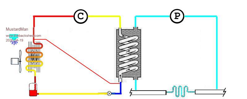
This was something I cobbled up a few weeks back to get me started on the screen layout and where things would fit, in a around-about sort of manner. Several changes still to go. It is made up from snippets of a couple of HVAC schematics I scraped from the internet.

It is 800x320 pixels (the border does not show on a white background, and my drawing has a white background), and it is missing detail - there are several valves & sensors which have yet to be added. My employer is farming the real drawing out to a graphic artist to do a vector drawing which will be later rasterised for this particular controller screen. The vector drawing will also be used for other devices (eg: smart phone, web page interface, etc) to give the user a consistent feel no matter how they interact with it.

When interacting with it, the full page (800x320 pixels) changes to allow input parameters to be entered, and then reverts back.

Today I coded up a couple of functions/subroutines (in basic) that can save the image as a "RLE" sequence using PEEK (VAR array(), offset) and POKE. Very slow, but basis for conversion to a Cfunction. RLE works well as there are not many colours, and big areas of the same colour.
 
paceman
Guru

Joined: 07/10/2011
Location: Australia
Posts: 1329
Posted: 04:50am 20 Apr 2020
Copy link to clipboard 
Print this post

@mustardMan

As @Turbo46 (Bill) mentioned above there was a thread in May '17 about flow simulation using MMBasic and MicroMites. I wrote a program with help from @disco4now (Gerry) to show the MM2 and MM+ simulating flow on a simple control diagram. I checked it again last night on the MM+ with a 4.3" SS1963 touch panel and apart from one small change that had to be made (using the GUI INTERRUPT command) it works fine.

There was some discussion about how to show some simple 'control' type grapics. Jim Hiley (@TassieJim) modded his Windows FontTweak program to facilitate this and it worked well enough to demo the technique. The original program didn't show the use of the 'objects' but I've posted it again below to show how it worked.

Note this was written mostly to show the 'flow-simulation' not the pump, valve etc. objects but the method is there. Gerry added in the 'flow speed' stuff and the 'touchscreen' mod to reverse direction and got rid of the blocking 'PAUSE' I had. Doing the flow simulation part keeps the processor fairly 'busy' but the graphics are quick.

Whoops, I've just noticed the version below is for the MM2 and 3" ILI9341 screen but no worries, it still runs OK on the MM+ with SS1963 4.3". Note you need to remove the GUI INTERRUPT command and de-comment the other two lines at the same location to run with the MM2.

Greg

  Quote  'FLUID FLOW SIMULATION  -  MMBasic V5.2 using the MX170 Micromite & ILI9341 LCD Display
'                          Greg Yaxley (paceman on TBS)
'-----------------------------------------------------------------------------------
'Modded using SETTIMER to update flows in the background.
'Touching the sreen will reverse the flows. Gerry Allardice (TBS disco4now)
'
'Note: the MMBasic OPTION table settings discoverable by the PEEK function (e.g. T_IRQ)
'can be found here: http://www.thebackshed.com/forum/forum_posts.asp?TID=8575
'and here: http://www.thebackshed.com/forum/forum_posts.asp?TID=9438&PN=1
'------------------------------------------
 CLS
 
CONST WHITE = RGB(WHITE)
 
CONST RED = RGB(RED)
 
CONST BLUE = RGB(BLUE)
 
CONST GREEN = RGB(GREEN)
 
CONST GRAY = RGB(GRAY)
 
CONST YELLOW = RGB(YELLOW)
 
 
DIM INTEGER stx,sty,finx,finy,diam
 
DIM INTEGER speed,direction,speedcounter
 
 
'Setup arrays to hold data for the pipes
 DIM INTEGER phase(10)   'The current write phase of each pipe display
 DIM INTEGER pipespeed(10)= (0,0,0,0,0,0,0,0,0,0,0)      'speed divider for pipes. 0 is stopped,
'                                                          1 is fastest. 9 is slowest
 DIM INTEGER flowdirection(10)= (0,0,0,0,0,0,0,0,0,0,0)  'direction of flow. -1 is reverse,
'                                                          anything else is forward or down  
 
Main:
 
CLS
 
BOX 70, 11, 60, 30, 2,WHITE,BLUE
 
TEXT 72, 12, "HEADER",,,,YELLOW,BLUE
 
BOX 241, 80, 40, 50, 2,WHITE,RED
 vtext(
"PANEL",290,76)                 'writes vertical text

' valve.bas 32x32
myBm$ = ""
myBm$ = myBm$+
CHR$(0)+CHR$(0)+CHR$(0)+CHR$(0)+CHR$(1)+CHR$(255)+CHR$(255)+CHR$(128)
myBm$ = myBm$+
CHR$(0)+CHR$(1)+CHR$(128)+CHR$(0)+CHR$(0)+CHR$(1)+CHR$(128)+CHR$(0)
myBm$ = myBm$+
CHR$(0)+CHR$(1)+CHR$(128)+CHR$(0)+CHR$(48)+CHR$(1)+CHR$(128)+CHR$(12)
myBm$ = myBm$+
CHR$(40)+CHR$(1)+CHR$(128)+CHR$(20)+CHR$(36)+CHR$(1)+CHR$(128)+CHR$(36)
myBm$ = myBm$+
CHR$(34)+CHR$(1)+CHR$(128)+CHR$(68)+CHR$(33)+CHR$(1)+CHR$(128)+CHR$(132)
myBm$ = myBm$+
CHR$(32)+CHR$(129)+CHR$(129)+CHR$(4)+CHR$(32)+CHR$(65)+CHR$(130)
myBm$ = myBm$+
CHR$(4)+CHR$(32)+CHR$(33)+CHR$(132)+CHR$(4)+CHR$(32)+CHR$(17)+CHR$(136)
myBm$ = myBm$+
CHR$(4)+CHR$(32)+CHR$(9)+CHR$(144)+CHR$(4)+CHR$(32)+CHR$(5)+CHR$(160)
myBm$ = myBm$+
CHR$(4)+CHR$(32)+CHR$(3)+CHR$(192)+CHR$(4)+CHR$(32)+CHR$(1)+CHR$(128)
myBm$ = myBm$+
CHR$(4)+CHR$(32)+CHR$(1)+CHR$(128)+CHR$(4)+CHR$(32)+CHR$(2)+CHR$(64)
myBm$ = myBm$+
CHR$(4)+CHR$(32)+CHR$(4)+CHR$(32)+CHR$(4)+CHR$(32)+CHR$(8)+CHR$(16)
myBm$ = myBm$+
CHR$(4)+CHR$(32)+CHR$(16)+CHR$(8)+CHR$(4)+CHR$(32)+CHR$(32)+CHR$(4)
myBm$ = myBm$+
CHR$(4)+CHR$(32)+CHR$(64)+CHR$(2)+CHR$(4)+CHR$(32)+CHR$(128)+CHR$(1)
myBm$ = myBm$+
CHR$(4)+CHR$(33)+CHR$(0)+CHR$(0)+CHR$(132)+CHR$(34)+CHR$(0)+CHR$(0)
myBm$ = myBm$+
CHR$(68)+CHR$(36)+CHR$(0)+CHR$(0)+CHR$(36)+CHR$(40)+CHR$(0)+CHR$(0)
myBm$ = myBm$+
CHR$(20)+CHR$(48)+CHR$(0)+CHR$(0)+CHR$(12)+CHR$(0)+CHR$(0)+CHR$(0)
myBm$ = myBm$+
CHR$(0)
' End Define bitmap
valve$ = myBm$
GUI BITMAP 87,88,valve$,32,32   'Draw the valve.

' pump 40x40.bas
myBm$ = ""
myBm$ = myBm$+
CHR$(0)+CHR$(0)+CHR$(0)+CHR$(0)+CHR$(0)+CHR$(0)+CHR$(0)+CHR$(63)
myBm$ = myBm$+
CHR$(128)+CHR$(0)+CHR$(0)+CHR$(1)+CHR$(192)+CHR$(112)+CHR$(0)+CHR$(0)
myBm$ = myBm$+
CHR$(6)+CHR$(0)+CHR$(12)+CHR$(0)+CHR$(0)+CHR$(24)+CHR$(0)+CHR$(3)
myBm$ = myBm$+
CHR$(0)+CHR$(0)+CHR$(32)+CHR$(0)+CHR$(0)+CHR$(128)+CHR$(0)+CHR$(64)
myBm$ = myBm$+
CHR$(0)+CHR$(0)+CHR$(64)+CHR$(0)+CHR$(128)+CHR$(0)+CHR$(0)+CHR$(32)
myBm$ = myBm$+
CHR$(1)+CHR$(0)+CHR$(0)+CHR$(0)+CHR$(16)+CHR$(1)+CHR$(0)+CHR$(0)
myBm$ = myBm$+
CHR$(0)+CHR$(16)+CHR$(2)+CHR$(0)+CHR$(0)+CHR$(0)+CHR$(8)+CHR$(2)
myBm$ = myBm$+
CHR$(0)+CHR$(0)+CHR$(0)+CHR$(8)+CHR$(4)+CHR$(0)+CHR$(0)+CHR$(0)+CHR$(4)
myBm$ = myBm$+
CHR$(4)+CHR$(0)+CHR$(0)+CHR$(0)+CHR$(4)+CHR$(8)+CHR$(0)+CHR$(0)+CHR$(0)
myBm$ = myBm$+
CHR$(4)+CHR$(8)+CHR$(0)+CHR$(0)+CHR$(0)+CHR$(2)+CHR$(8)+CHR$(0)+CHR$(0)
myBm$ = myBm$+
CHR$(0)+CHR$(2)+CHR$(8)+CHR$(0)+CHR$(0)+CHR$(0)+CHR$(2)+CHR$(4)+CHR$(0)
myBm$ = myBm$+
CHR$(0)+CHR$(0)+CHR$(2)+CHR$(4)+CHR$(0)+CHR$(0)+CHR$(0)+CHR$(2)+CHR$(4)
myBm$ = myBm$+
CHR$(0)+CHR$(0)+CHR$(0)+CHR$(2)+CHR$(2)+CHR$(0)+CHR$(0)+CHR$(0)+CHR$(4)
myBm$ = myBm$+
CHR$(2)+CHR$(0)+CHR$(0)+CHR$(0)+CHR$(4)+CHR$(1)+CHR$(0)+CHR$(0)+CHR$(0)
myBm$ = myBm$+
CHR$(4)+CHR$(193)+CHR$(128)+CHR$(0)+CHR$(0)+CHR$(8)+CHR$(192)+CHR$(224)
myBm$ = myBm$+
CHR$(0)+CHR$(0)+CHR$(8)+CHR$(255)+CHR$(248)+CHR$(0)+CHR$(0)+CHR$(8)
myBm$ = myBm$+
CHR$(192)+CHR$(0)+CHR$(0)+CHR$(0)+CHR$(16)+CHR$(192)+CHR$(0)+CHR$(0)
myBm$ = myBm$+
CHR$(0)+CHR$(16)+CHR$(192)+CHR$(0)+CHR$(0)+CHR$(0)+CHR$(48)+CHR$(192)
myBm$ = myBm$+
CHR$(0)+CHR$(0)+CHR$(0)+CHR$(96)+CHR$(192)+CHR$(0)+CHR$(0)+CHR$(0)
myBm$ = myBm$+
CHR$(224)+CHR$(192)+CHR$(0)+CHR$(0)+CHR$(3)+CHR$(192)+CHR$(192)+CHR$(0)
myBm$ = myBm$+
CHR$(0)+CHR$(15)+CHR$(192)+CHR$(192)+CHR$(0)+CHR$(0)+CHR$(127)+CHR$(224)
myBm$ = myBm$+
CHR$(255)+CHR$(255)+CHR$(255)+CHR$(255)+CHR$(240)+CHR$(192)+CHR$(127)
myBm$ = myBm$+
CHR$(255)+CHR$(255)+CHR$(248)+CHR$(192)+CHR$(255)+CHR$(255)+CHR$(255)
myBm$ = myBm$+
CHR$(252)+CHR$(1)+CHR$(255)+CHR$(255)+CHR$(255)+CHR$(254)+CHR$(0)
myBm$ = myBm$+
CHR$(0)+CHR$(0)+CHR$(0)+CHR$(0)
' End Define bitmap
pump$ = myBm$
GUI BITMAP 240,172,pump$,40,40      'Draw the pump.

' Start the settick timer to run as our update thread
SETTICK 10,BackGroundThread,4
' Setup touch interrupt subroutine for MM+
GUI INTERRUPT touchdown

' T_IRQ = peek(byte peek(word &H9D000090) + 23) 'read MM2 Touch Interrupt. See Introd'n.
' SetPin T_IRQ, INTL, TouchDown                 'set interrupt on MM2 to detect touch.
'Note: the two lines above are only applicable to the Micromite2, not the Micromite+

 
'setup pipe initial direction and speed
 flowdirection(3)=-1
 flowdirection(
4)=-1
 flowdirection(
5)=-1
 pipespeed(
0)=1
 pipespeed(
1)=2
 pipespeed(
2)=1
 pipespeed(
3)=4
 pipespeed(
4)=1
 pipespeed(
5)=5
 
DO
 
 
LOOP
 
END
 
'----------------------------------------------
SUB BackGroundThread
   
SETTICK 0,0,4                        'disable the tick timer while its processing
   speedcounter = speedcounter+1
   flow(
0,10,24,260,24,5,WHITE,BLUE)    ' call each pipe and update if required
   flow(1,260,24,260,80,5,WHITE,BLUE)
   flow(
2,260,130,260,188,5,WHITE,RED)
   flow(
3,100,201,239,201,5,WHITE,RED)
   flow(
4,100,105,100,200,5,WHITE,RED)
   flow(
5,10,103,240,103,5,BLUE,RED)
   
're enable the tick timer
  SETTICK 20,BackGroundThread,4
END SUB

SUB TouchDown
 
'? touch(x)
  FOR x =0 TO 5
   
IF flowdirection(x) = -1 THEN
      flowdirection(x) =
0
   
ELSE
      flowdirection(x) = -
1
   
ENDIF  
 
NEXT x
END SUB

SUB flow(pipeno,stx,sty,finx,finy,diam,cull1%,cull2%)
 
 
'Fluid flow is indicated as alternate coloured segments - forward, reverse or stationary.
 'Forward flow (direction) is the default and defined as left to right and top to bottom of screen.
 'Reverse flow (direction = -1) is right to left or bottom to top of screen.
 'Pipe start/finish positions must be entered left to right or top to bottom of screen.
 'Flow simulation derives from the part-segment "offset" alternately displayed at the start of
 'the "pipe" and the "speed" pause between segment movements.
 'The segment length variable can be varied, or fixed in the code.

 
LOCAL INTEGER tempx, tempy, segment=10, offset, count
 
LOCAL INTEGER endfirstseg, stsecseg, endsecseg
 count = phase(pipeno)              
'get current count for this pipe
 speed = pipespeed(pipeno)
 direction = flowdirection(pipeno)
 
 
IF speed <> 0 THEN
   
IF speedcounter\speed<>speedcounter/speed THEN EXIT SUB
 
ELSE
    count =
0  
 
END IF
 
 
IF stx-finx AND sty-finy <> 0 THEN PRINT "Pipe must be vertical or horizontal": END
 
IF stx>finx OR sty>finy THEN PRINT "Pipes must be defined left to right or top to bottom": END
 offset = segment\
2   'flow simulation is best when "offset" is about half the segment length
 IF stx = finx THEN GOTO Vertical   'test for vertical pipe
 
Horizontal:
 tempx = stx
 
   
IF direction = -1 THEN
     
IF count = 1 OR count = 3 THEN
      swap(cull1%,cull2%)            
'for reverse flow to maintain correct simulation
     END IF
   
END IF
   
   stx = stx + count*offset  
'offset the start of 'normal' segment posns
   ' write the pipe segments    
   DO
     endfirstseg = stx + segment: stsecseg = endfirstseg+
1:  endsecseg = stsecseg + segment
     
IF endfirstseg >= finx THEN LINE stx, sty, finx, finy, diam, cull1%: EXIT DO
     
LINE stx, sty, endfirstseg, finy, diam, cull1%
     
IF endsecseg >= finx THEN LINE stsecseg, sty, finx, finy, diam, cull2%: EXIT DO
     
LINE stsecseg, sty, endsecseg, finy, diam, cull2%
     stx = endsecseg +
1     'increment next segment-pair start position.
   LOOP
   
' now fix up the first segement
   stx = tempx
   
IF direction = -1 THEN
     
IF count = 1 OR count = 2  THEN  
           
LINE stx, sty, stx + count*offset, finy, diam, cull2%
     
END IF
     
IF  count = 3  THEN      
         
LINE stx, sty, stx + offset, finy, diam, cull1%
         
LINE stx+offset, sty, stx + count*offset, finy, diam, cull2%
     
END IF
   
ELSE    
     
IF count = 1 OR count = 2  THEN  
         
LINE stx, sty, stx + count*offset, finy, diam, cull2%    
     
END IF
     
IF count = 3  THEN
         
LINE stx, sty, stx + offset, finy, diam, cull1%  
         
LINE stx+offset, sty, stx + count*offset, finy, diam, cull2%  
     
END IF  
   
END IF
   
   
'setup for next write
   count = count+1
   
IF count=4 THEN count=0
   phase(pipeno) = count

 
EXIT SUB
 
Vertical:
 tempy = sty
   
IF direction = -1 THEN
     
IF count=1 OR count=3 THEN
      swap(cull1%,cull2%)
'for reverse flow to maintain correct simulation
     END IF
   
END IF
   
   sty = sty + count*offset  
'offset the start of 'normal' segment posns
   ' write the pipe segements    
   DO
     endfirstseg = sty + segment: stsecseg = endfirstseg+
1:  endsecseg = stsecseg + segment
     
IF endfirstseg >= finy THEN LINE stx, sty, finx, finy, diam, cull1%: EXIT DO
     
LINE stx, sty, stx, endfirstseg, diam, cull1%
     
IF endsecseg >= finy THEN LINE stx, stsecseg, finx, finy, diam, cull2%: EXIT DO
     
LINE stx, stsecseg, finx, endsecseg, diam, cull2%
     sty = endsecseg +
1    'increment next segment-pair start position
   LOOP
   
' now fix up the first segement
   sty = tempy
   
IF direction = -1 THEN
     
IF count = 1 OR count = 2  THEN  
         
LINE stx, sty, finx , sty+ count*offset, diam, cull2%
     
END IF
     
IF  count=3  THEN      
         
LINE stx, sty, finx, sty + offset, diam, cull1%
         
LINE stx, sty+offset , finx, sty + count*offset, diam, cull2%
     
END IF
   
ELSE    
     
IF count = 1 OR count = 2  THEN  
         
LINE stx, sty, finx, sty + count*offset, diam, cull2%    
     
END IF
     
IF count = 3  THEN
         
LINE stx, sty, finx, sty + offset, diam, cull1%  
         
LINE stx, sty+offset, finx,  sty + count*offset, diam, cull2%  
     
END IF  
   
END IF  
     
   count = count+
1            'setup for next write
   IF count=4 THEN count=0
   phase(pipeno) = count

END SUB
 
'----------------------
SUB Swap a%, b%
 
LOCAL t%
 t% = a%: a% = b%: b% = t%
END SUB
 
'----------------------
SUB vtext(name$,x,y)
FOR i=0 TO LEN(name$)-1
TEXT x, y+i*(MM.FONTHEIGHT-2), MID$(name$,i+1,1),CT,,,,-1
NEXT
END SUB
'------------------------

Edited 2020-04-20 14:58 by paceman
 
Print this page


To reply to this topic, you need to log in.

The Back Shed's forum code is written, and hosted, in Australia.
© JAQ Software 2025