
|
|
Forum Index : Microcontroller and PC projects : Colour Maximite Case/Box (How to ?)
| Author | Message | ||||
| matherp Guru Joined: 11/12/2012 Location: United KingdomPosts: 10273 |
I assume all countries have examples of dual switch light wiring where either switch is on or off depending on the state of the other. How do the switch direction mafia cope with those?  |
||||
| WhiteWizzard Guru Joined: 05/04/2013 Location: United KingdomPosts: 2934 |
For people wanting switch UP to be power ON, simply turn your CMM2 upside-down! The CMM2 will still work if inverted!! I will be creating the CMM2 panels from PCB just like I did for the CMM1 kits that I supply. Similar to the CMM1 panels, they will not have any writing on them - they will just be blank (and in a black colour, matt finish). WW Edited 2020-05-23 17:18 by WhiteWizzard |
||||
| matherp Guru Joined: 11/12/2012 Location: United KingdomPosts: 10273 |
Gerbers for panels based on my laser cut versions. Use, abuse or ignore at your own risk backpanel.zip frontpanel.zip |
||||
| Poppy Guru Joined: 25/07/2019 Location: GermanyPosts: 486 |
Thanks!  I don┤t know what they look like right now, but generally this way gives more opportunities for styling than just getting those panels readily cut. Probably this could be a way to pimp up the whole case. Just some imaginations: ... painting the outer shells glossy black and the panels do have some etched out copper styling including labels and frames/borders, being finished glossy and clear. This could look quite classy ... ... or making some optical setup to make it look like steam punk. ... or whatever starting up some individual case modding, just like it is done in a bigger way for PC┤s but without overstating it, so easily keeping it right on top of the basic case. Andre ... such a GURU? | ||||
bigmik Guru Joined: 20/06/2011 Location: AustraliaPosts: 2949 |
GÆday blokes, (and shielas if any are viewing this), It is much simpler than that.. Use a sharp knife heated over a gas stove and cut the rectangular bits away and carefully drill the round holes.. Then print your fascia panels on photo paper and laminate it. Affix your fascia to the cut panels with thin double sided tape .. any mistakes in the plastic will be hidden by the fascia. This has the advantage of not only being very cheap but looks professional and you can have pretty colours and clear text.. it is up to how good your artwork is.. Regards, Mick Mick's uMite Stuff can be found >>> HERE (Kindly hosted by Dontronics) <<< |
||||
| Poppy Guru Joined: 25/07/2019 Location: GermanyPosts: 486 |
Good idea Mick, I think this is the easiest practical way! I am also thinking about getting this one: https://www.proxxon.com/en/micromot/28530.php a tiny electrical jigsaw, this brand offers many great little machines, some of them I already got, but none supporting my particular needs for the panels yet. Edited 2020-05-23 23:29 by Poppy Andre ... such a GURU? | ||||
| twofingers Guru Joined: 02/06/2014 Location: GermanyPosts: 1579 |
Hi, I converted Peters gerbers - thanks Peter! - to DXF and STL (h=2mm) for 3D printing. backpanel - Bottom Copper.zip frontpanel - Bottom Copper.zip 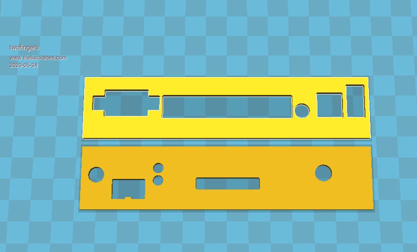 I'm not sure if that helps? Regards Michael causality ŌēĀ correlation ŌēĀ coincidence |
||||
| matherp Guru Joined: 11/12/2012 Location: United KingdomPosts: 10273 |
Thanks for posting the STL conversions. Attached is the original dxf file which hopefully is the same. CMM2V2.1.zip |
||||
| twofingers Guru Joined: 02/06/2014 Location: GermanyPosts: 1579 |
HI Peter, thanks for the "original" DXF file. I used gerbview (eval) to convert. Your file works better with Fusion360! Regards Michael causality ŌēĀ correlation ŌēĀ coincidence |
||||
| bigmik Guru Joined: 20/06/2011 Location: AustraliaPosts: 2949 |
GDay Lads, Is anyone able to convert to a more usable format like PDF or any standard format in as high a quality as possible (within reason) so I can photo-shop a master for cutting? EDIT ** Ignore that! I literally found them 1 minute later in the construction pack.. Gee I must be getting old. Thanks in advance Kind Regards Mick Edited 2020-05-24 14:23 by bigmik Mick's uMite Stuff can be found >>> HERE (Kindly hosted by Dontronics) <<< |
||||
| BrianP Senior Member Joined: 30/03/2017 Location: AustraliaPosts: 292 |
Sorry to bring up switches again... After some profound thought, & I really hate to say it, Paul_L & his fellow countrymen (& girls) may in fact have the correct approach  If we start from the beginning, the equipment will be "down" i.e. "off" Turn it on & it will change to an "up" state i.e. "on" Seems more logical in a weird sort of way... As you can see I have expended a huge amount of scarce brain power to arrive at this conclusion  B |
||||
| Geoffg Guru Joined: 06/06/2011 Location: AustraliaPosts: 3286 |
All of us are (and I also just updated the Construction Pack)! Geoff Graham - http://geoffg.net |
||||
| Poppy Guru Joined: 25/07/2019 Location: GermanyPosts: 486 |
... or we all have just to listen to Joe┤s Mom [> 3:31]  Andre ... such a GURU? Andre ... such a GURU? | ||||
| matherp Guru Joined: 11/12/2012 Location: United KingdomPosts: 10273 |
 Probably cheaper elsewhere but totally compatible with both PCB footprint and panel cutout |
||||
| Poppy Guru Joined: 25/07/2019 Location: GermanyPosts: 486 |
A simple Toggle Switch should also do, one like this: Simple Toggle Switch just soldered to some wire and screwed to the panel. And if you put a rubber boot on it, it can look quite nice: Always use a Rubber! Ā PS: And it can be screwed in upside down or downside up, just depending on the wiring inside. Edited 2020-05-24 22:37 by Poppy Andre ... such a GURU? | ||||
| The Back Shed's forum code is written, and hosted, in Australia. | © JAQ Software 2025 |
