
|
|
Forum Index : Microcontroller and PC projects : How can I capture this data-stream?(non-standard)
| Author | Message | ||||
| robert.rozee Guru Joined: 31/12/2012 Location: New ZealandPosts: 2437 |
revised version. moved getcode into main body, handle pulse lengths as pairs (short,long or long,short) so no need to calculate a threshold value, other bits tidied up, outputs the code as a 6-digit hex value. is now more tolerant of CPU speed and seems to work ok with CPU 40. i also see we have a PULSIN function in micromite basic, which could possibly simplify things even further. will experiment with this next. cheers, rob :-) CPU 48 Option break 0 SetPin 22, DIN Dim times(150) Dim keylist%(20) ' main program begins here For I=149 To 150: times(I)=9999: Next I For I=1 To 20: keylist%(I)=&hDEADC0DE: Next I keylist%(15)=&h0B1864 keylist%(16)=&h0B1868 keylist%(17)=&h0B186C keylist%(18)=&h089964 keylist%(19)=&h089968 keylist%(20)=&h08996C Print "press 'esc' to exit, space bar to add fob code, '?' to list saved codes" Do ' retrieve pulse timings from SYN470R receiver state=0 For I=0 To 148 count=0 Do :count=count+1:Loop Until (Pin(22)=state) times(I)=count state=Not state Next I ' find maximum time value, use 1/4 of this as threshold for start/end pulse tv=0 For I=1 To 148:tv=Max(tv,times(I)): Next I tv=tv/4 ' find beginning and end of a (possibly) valid code segment I=1 Do While times(I)<(tv): I=I+1:Loop I1=I: I=I+1 Do While times(I)<(tv): I=I+1:Loop I2=I If (I2-I1-1)<>49 Then Print ".";: GoTo skip code%=0 For I=I1+1 To I2-2 Step 2 Print Str$(times(I),0) "|" Str$(times(I+1),0) " "; If Pos>40) Then Print code%=code%<<1 If times(I)>times(I+1) Then code%=code%+1 Next I Print times(I2-1) Print I1, I2,, "(" Str$(I2-I1-1,0) ")",, times(I1), times(I2),, Str$(tv,0,1) Print Hex$(code%, 6) Print Bin$(code%, 24) ' check for a match to a saved code, beep if found For I=1 To 20 If code%=keylist%(I) Then Print Chr$(7); Next I Pause (900) skip: ' press space bar to add fob code to list (max 20) key$=Inkey$ If key$=" " Then keylist%(index+1)=code% index=(index+1) Mod 20 EndIf ' press '?' to print out the list of saved fob codes If key$="?" Then For I=1 To 20 If keylist%(I)<>&hDEADC0DE Then Print Hex$(keylist%(I), 6) Next I EndIf If key$=Chr$(27) Then Exit Do key$="" Loop |
||||
Grogster Admin Group Joined: 31/12/2012 Location: New ZealandPosts: 9593 |
Have to go to a job now, but I just HAD to try out your 1st code - and then I see you have already added another one!  Anyway, here is the result of my pressing a button using your 1st code: 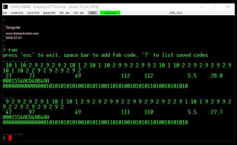 I pressed the same button twice, and I note I get exactly the same code back, so that is confirming that the 1st code you posted IS giving consistent results.  I have to go to work now, but I will be back to try your latest code later!!!!  Smoke makes things work. When the smoke gets out, it stops! |
||||
| robert.rozee Guru Joined: 31/12/2012 Location: New ZealandPosts: 2437 |
here's an even 'better' version, using PULSIN to measure just the negative pulses. the down side is that it isn't self-calibrating. cutoff points are hard-wired at 5000us and 600us. so it may not work right with non-1527 key fobs. cheers, rob :-) CPU 48 Option break 0 SetPin 22, DIN Dim times(60) Dim keylist%(20) ' main program begins here For I=59 To 60: times(I)=9999: Next I For I=1 To 20: keylist%(I)=&hDEADC0DE: Next I keylist%(15)=&h0B1864 keylist%(16)=&h0B1868 keylist%(17)=&h0B186C keylist%(18)=&h089964 keylist%(19)=&h089968 keylist%(20)=&h08996C Print "press 'esc' to exit, space bar to add fob code, '?' to list saved codes" Do ' retrieve pulse timings from SYN470R receiver For I=0 To 58: times(I)=Pulsin(22, 0): Next I ' find beginning and end of a (possibly) valid code segment I=1 Do While times(I)<(5000): I=I+1:Loop I1=I: I=I+1 Do While times(I)<(5000): I=I+1:Loop I2=I If (I2-I1-1)<>24 Then Print ".";: GoTo skip code%=0 For I=I1+1 To I2-1 Print Str$(Int(times(I)),5); If Pos>40 Then Print code%=code%<<1 If times(I)<600 Then code%=code%+1 Next I Print I1, I2,, "(" Str$(I2-I1-1,0) ")",, times(I1), times(I2) Print Hex$(code%, 6) Print Bin$(code%, 24) ' check for a match to a saved code, beep if found For I=1 To 20 If code%=keylist%(I) Then Print Chr$(7); Next I Pause (900) skip: ' press space bar to add fob code to list (max 20) key$=Inkey$ If key$=" " Then keylist%(index+1)=code% index=(index+1) Mod 20 EndIf ' press '?' to print out the list of saved fob codes If key$="?" Then For I=1 To 20 If keylist%(I)<>&hDEADC0DE Then Print Hex$(keylist%(I), 6) Next I EndIf If key$=Chr$(27) Then Exit Do key$="" Loop |
||||
| Grogster Admin Group Joined: 31/12/2012 Location: New ZealandPosts: 9593 |
Wonderful! Here is a screenshot from your 2nd code: 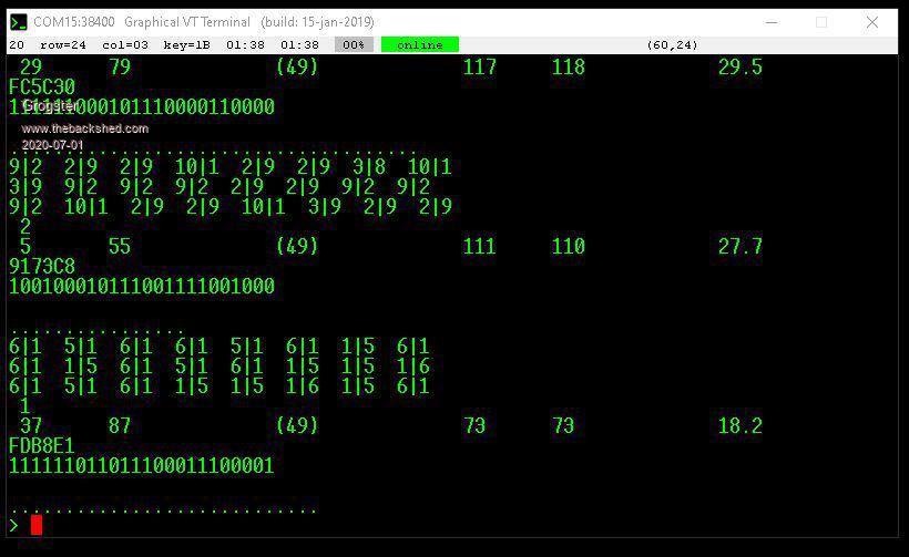 This one is MUCH faster then the 1st code. I tried three different buttons on this one. Came here to post photo, and you have ANOTHER one for me to try!  I have yet another job to go to now, but I will be back later tonight to post the results of your latest(3rd) code. Smoke makes things work. When the smoke gets out, it stops! |
||||
| Grogster Admin Group Joined: 31/12/2012 Location: New ZealandPosts: 9593 |
OK, here is the image of Rob's 3rd code: 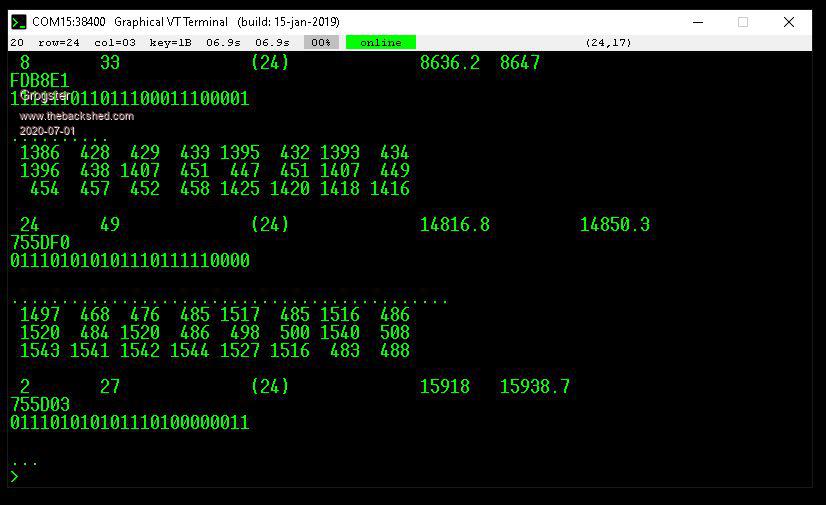 The first button is a 1527 encoder, the 2nd and 3rd buttons are 2264 encoders with solder-blob addressing.(same address, different D0-D3 bit blob settings) This is really excellent. Can you explain what the columns of debug information are, and the line that is 2,27,(24),15918,15938.7 in my image are? The HEX code for the button follow that, and then the last line is the binary code for the same button, so I follow that no problems, but would like to understand what the other debug information represents. Smoke makes things work. When the smoke gets out, it stops! |
||||
TassyJim Guru Joined: 07/08/2011 Location: AustraliaPosts: 6269 |
The first 24 numbers are the times of each bit decoded. Above 1000 indicates a 0 and below 1000 indicates a 1 On the next row are the starting and ending array slots for the two long pulses indication start and end. the (24) is the count of bits decoded between the start and stop which should equal the number of readings in the above array. It does. the last two numbers are the length of the start and stop long pulses in microseconds. I think I have it right. Jim VK7JH MMedit |
||||
| Grogster Admin Group Joined: 31/12/2012 Location: New ZealandPosts: 9593 |
Excellent, thank you for that. It helps me understand what is going on. Smoke makes things work. When the smoke gets out, it stops! |
||||
| robert.rozee Guru Joined: 31/12/2012 Location: New ZealandPosts: 2437 |
TassyJim's explanation is pretty much spot on. following is a quick guide to how both versions (2 and 3) work. terminology is: BREAK = 8-10ms negative pulse, SHORT = 300us pulse (typically < 600us) LONG = 900us pulse ( typically > 600us) version 2 we time the length of 149 positive and negative pulses, using a simple counter loop. we do not need to bother keeping track of which ones are positive and which ones are negative, as we know that there are really long BREAK pulses between code blocks. these BREAKJ pulses are negative, so we can later on work out the polarity of the rest of the pulses from there. this is the code that collects the 149 pulse lengths: state=0 For I=0 To 148 count=0 Do :count=count+1:Loop Until (Pin(22)=state) times(I)=count state=Not state Next I the value of state switches us back and forth between looking for positive and looking for negative pulses after each pulse has been timed. we also place a couple of 'dummy' counts at the end of the times array (of 9999), so that when we search through the data further down in the code, the search always terminates. there are neater ways that this could have been done. also note that if there is NO data coming from the receiver, then this code will loop forever - it relies upon the random data that the receiver produces when no signal is present to work correctly. the sorts of numbers we see with an MX170 are: SHORT -> 1 or 2 passes through the counter loop, LONG -> 4 or 5 passes through the counter loop, BREAK -> 70 or so passes through the counter loop. numbers when run on an MX470 would appear to be 2-3, 9-10, and 110. we next process the collected data: (1) search through the captured timing data to find the longest pulse captured, which corresponds to the one of the 8-10ms BREAKs between code blocks. we divide this found value by 4 (dividing by 2 would have been safer) and use it to pick out the start and end of one single code block. because we have collected 148 samples, we know that there should be at least ONE valid code block in there if a fob transmitting: ' find maximum time value, use 1/4 of this as threshold for start/end pulse tv=0 For I=1 To 148:tv=Max(tv,times(I)): Next I tv=tv/4 ' find beginning and end of a (possibly) valid code segment I=1 Do While times(I)<(tv): I=I+1:Loop I1=I: I=I+1 Do While times(I)<(tv): I=I+1:Loop I2=I (2) check that the code block is the right length - 49 timed periods (the number of pulses will always be odd, there being an extra 'dummy' positive pulse at the end). if the number of periods is not right, we print a "." and go back to collecting data. (3) looking at pairs of time values, LONG followed by SHORT = 1, SHORT followed by LONG = 0. the first time value in a pair always corresponds to a positive pulse, while the second corresponds to a negative pulse. we display these in the diagnostics output as pairs of numbers with a "|" between them. one number should always be about 4x the other, ie "1|5" or "9|2", with higher numbers better from the perspective of the code being more reliable. outside of the for...next loop we print the value for the last (dummy) pulse just for completeness. the next line of diagnostics output consists of: index of first BREAK, index of second BREAK, "(" number of pulses including the 'dummy' one ")" loop counter for first BREAK, loop counter for second BREAK, calculated threshold value used to locating BREAKS. version 3 we time the length of 59 negative pulses using the PULSIN function. we know from the 1527 specifications that with a valid transmission the lengths of pulses should be around about 300us, 900us, and 9ms. PULSIN returns the length in microseconds, and times out after 100ms - so the code does not lock up if there is no activity on pin 22: For I=0 To 58: times(I)=Pulsin(22, 0): Next I as in version 2, we search for the BREAK pulses, but just use the criterion of > 5000us. we check for 24 negative pulses captured between the BREAK pulses, and if the number of periods is not right, we print a "." and go back to collecting data. next, we loop through the 24 measured negative pulses (these are the second pulse in each of the pairs talked about for version 2 of the code) - if a pulse is <600us this corresponds to a code bit of "1", otherwise the code bit is a "0". for diagnostics, we print out the length of each pulse, which is a value in microseconds. is version 3, on the diagnostics line the last two numbers are the lengths of the two BREAKs in microseconds. i'll work on cleaning up the code a bit more, removing the diagnostics, removing the save fob code option (which was useful for testing), and add a check that the receiver module is working. cheers, rob :-) |
||||
| robert.rozee Guru Joined: 31/12/2012 Location: New ZealandPosts: 2437 |
here we go, a final version: CPU 48 Option break 0 SetPin 22, DIN Dim times(60) Do �T=Timer �For I=0 To 60:times(I)=Pulsin(22, 0):Next I �If Timer-T>2000 Then Print "receiver fault" �I1=0: I2=0 �For I=1 To 60 � �If (times(I)>4000) And (I1=0) Then I1=I �Next I �For I=I1+1 To 60 � �If (times(I)>4000) And (I2=0) Then I2=I �Next I �If (I2<>0) And (I2-I1-1)=24 Then � �threshold=64*times(I1)/992 � �code%=0 � �For I=I1+1 To I2-1 � � �code%=code%<<1 � � �If times(I)<threshold Then code%=code%+1 � �Next I ' � For I=I1 To I2: Print times(I),: Next I:Print ' � Print I1, I2,, "(" Str$(I2-I1-1,0) ")",, times(I1), times(I2), threshold � �Print Hex$(code%, 6) ' � Print Bin$(code%, 24) �End If Loop note the line: threshold=64*times(I1)/992 this adjusts the threshold according to the width of the BLANK pulse preceding the code block, following the timing specifications of the RT1527 and PT2262; BLANK pulse is 1024-32=992 units wide, SHORT pulses are 32 units wide, LONG pulses are 32*3=96 units wide. ADDENDUM: we don't use the trailing BLANK pulse, as the button on the key fob may have been released during this pulse, considerably extending the pulse (as seen by the receiver) and resulting in an excessively high threshold value causing the fob code appearing to be 0xFFFFFF cheers, rob � :-) Edited 2020-07-03 22:38 by robert.rozee |
||||
Quazee137 Guru Joined: 07/08/2016 Location: United StatesPosts: 593 |
I was going through some old saved youtube videos and found this Hacking Radio some of the tools and methodology may be of use for any one playing with radio and digital decoding/coding of signals. |
||||
| Grogster Admin Group Joined: 31/12/2012 Location: New ZealandPosts: 9593 |
@ robert_rozee: Thanks for that extra excellent description of what is going on. I owe you a big jug of the beer of your choice!  I have customised your latest code, so it now does everything I need: ...and I have a PCB being made for it now: 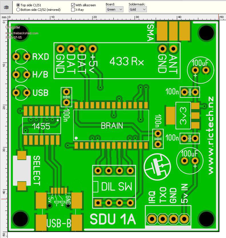 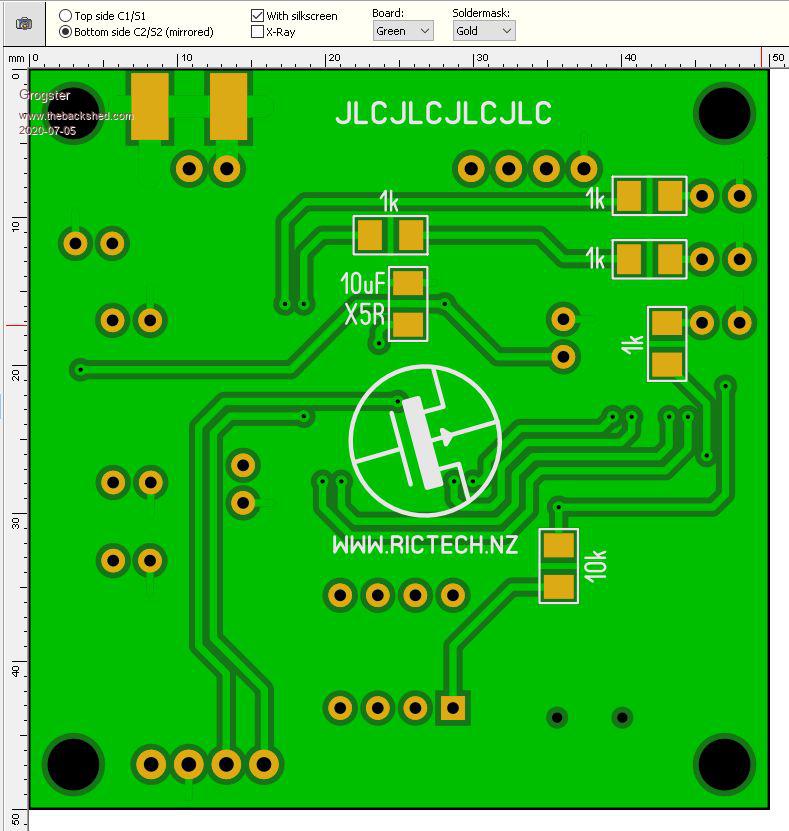 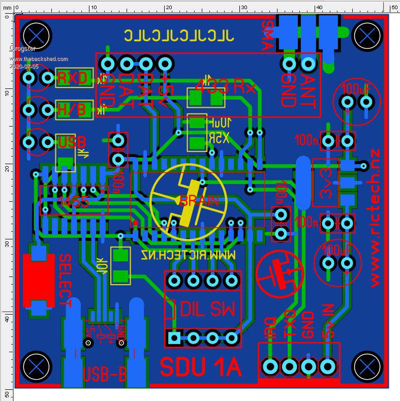 Smoke makes things work. When the smoke gets out, it stops! |
||||
| CaptainBoing Guru Joined: 07/09/2016 Location: United KingdomPosts: 2170 |
Cheers for that link Q quite scary and a sombre lesson in why we should use encryption for even the most basic comms between units. |
||||
| Grogster Admin Group Joined: 31/12/2012 Location: New ZealandPosts: 9593 |
PCB's have arrived, so I have built one. 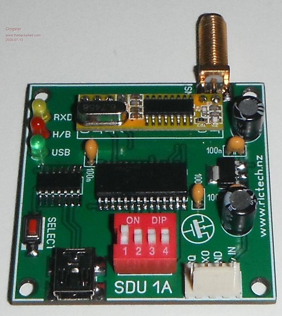 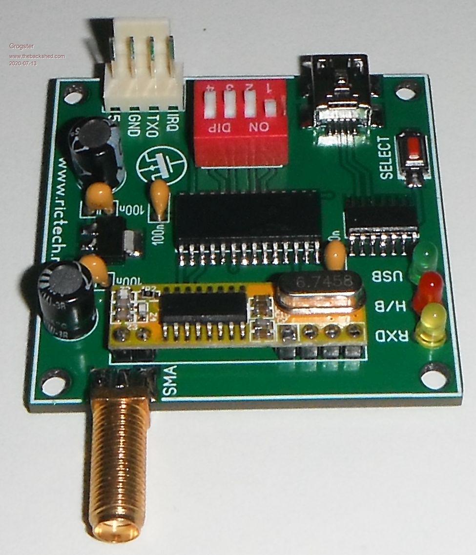 Worked on the very first attempt. Thanks to all who have help with this, but extra special thanks to robert.rozee for all his code that I was then able to customise to my purposes. If this is something that anyone else would like to have, I can put it up on my website as either a finished programmed unit, or as a construction pack with gerbers, rob's code and BOM etc. Reply here if you want either of those options. Smoke makes things work. When the smoke gets out, it stops! |
||||
| The Back Shed's forum code is written, and hosted, in Australia. | © JAQ Software 2025 |
