
|
|
Forum Index : Microcontroller and PC projects : CMM2 clone PCB
| Page 1 of 2 |
|||||
| Author | Message | ||||
manawyrm Newbie Joined: 30/07/2020 Location: GermanyPosts: 5 |
Hi, in the spirit of the good old homecomputers, I've designed my own CMM2 PCB and wanted to show it here: https://github.com/Manawyrm/CMM2-JLC#readme 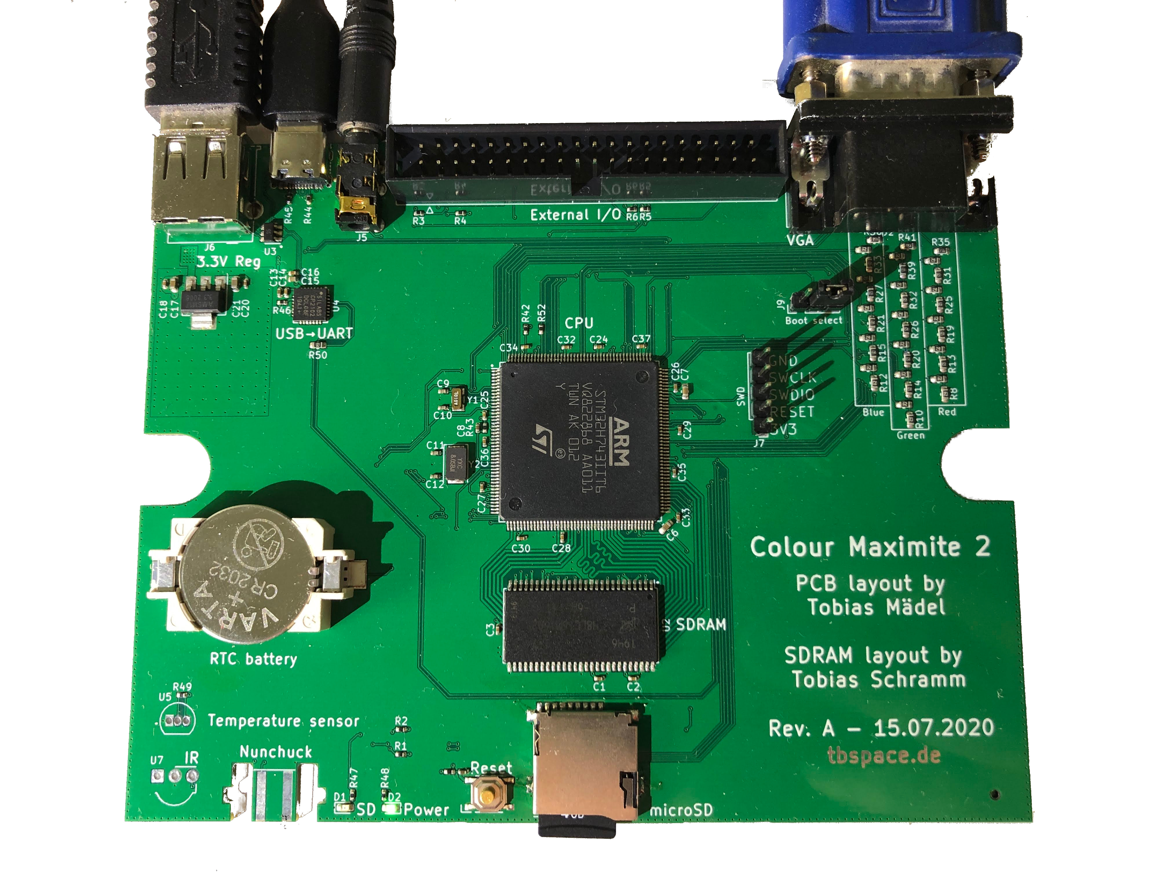 The schematic, board layout and production files are open source and can be found at: https://github.com/Manawyrm/CMM2-JLC/tree/master/gerbers/RevB/CMM2-JLC There's an interactive board viewer at: https://tbspace.de/content/downloads/ibom_cmm2_revb.html I've designed the board to be machine-assembled, everything except the few connectors can be ordered directly from a supplier like JLC, already assembled. It's a 4-layer design, with signal layers on the top and bottom, ground and power on the inner layers. To my great surprise, the board worked first try. Greetings from Germany, Tobias https://tbspace.de |
||||
| Womble Senior Member Joined: 09/07/2020 Location: United KingdomPosts: 267 |
Interesting  Is that USB-C for the power and console connection ? and a through hole audio socket ? I note it has a 400Mhz H7 chip. Might cause some out of joint noses and bruised toes though. |
||||
| Andrew_G Guru Joined: 18/10/2016 Location: AustraliaPosts: 883 |
Hi Tobias, Welcome! Very interesting first post. A couple of questions: - why? (the other PCB design and all its Gerbers are freely available) - how does one secure it to a case? Cheers, Andrew |
||||
| Atomizer_Zero Senior Member Joined: 04/07/2020 Location: United KingdomPosts: 134 |
I don't fully understand why either. I mean, it's cool that you've done it but.. The connectors for usb, usb c and audio all look a bit close together.. bit of a squeeze. Lots of empty space on the board, so potentially a different board design, maybe for a smaller case, could have been done. Or could have built in a vga to hdmi conversion circuit and had hdmi out possibly.. Either way, some interesting changes to the usual board. Nice job. |
||||
Grogster Admin Group Joined: 31/12/2012 Location: New ZealandPosts: 10000 |
Nice looking board.  I note you have put in little PCB 'Wavy track' inductors on three of the lines to the SDRAM chip. What made you decide to do that, or did your PCB software decide that for you for some reason? Smoke makes things work. When the smoke gets out, it stops! |
||||
| lizby Guru Joined: 17/05/2016 Location: United StatesPosts: 3829 |
This is very interesting. If I did it right, I just ordered 2 assembled boards (without connectors) for $123USD (after a $7 SMT coupon discount), counting express shipping. I had to add the size--I trust 130mm x 100mm is correct? Thank you for your effort and for generously providing this to the CMM2 community. PicoMite, Armmite F4, SensorKits, MMBasic Hardware, Games, etc. on FOTS |
||||
| vegipete Guru Joined: 29/01/2013 Location: CanadaPosts: 1182 |
Geil. Looks nice. I notice the I/O connector is numbered per industry standard, not as per CMM2 standard. Are there or would there be any frequency stability issues given your choice of an 8MHz crystal instead of the oscillator that is successfully fixing the video output of many Waveshare based CMM2s? Visit Vegipete's *Mite Library for cool programs. |
||||
| vegipete Guru Joined: 29/01/2013 Location: CanadaPosts: 1182 |
A bunch more tracks you can't see are wavy too. From reading the Github notes, this is done to ensure the tracks are the same length so that parallel signals stay synchronized. Visit Vegipete's *Mite Library for cool programs. |
||||
| manawyrm Newbie Joined: 30/07/2020 Location: GermanyPosts: 5 |
Hi, Yes, the USB-C replaces the old USB-B connector. I happen to have a lot of USB-C cables and I'm quite a fan of the new standard. Well, mostly to learn a bit more PCB design skills (the SDRAM layout was a first for me). I've also wanted to play with the bigger STM32 chips for a while now and figured this might be an ideal candidate. I also didn't want to solder the board myself and so it's optimized for assembly directly at JLC. About the case: I don't have one of the cases and sort of forgot about adding mounting holes. To be honest: I didn't expect RevA to just work out of the box. I wanted to stay somewhat true to the original layout with all the port on the back and front instead of the sides... Thanks! At the speeds the SDRAM can be running at, signal delay through the trace length becomes a real issue. All the traces shouldn't differ more than ~10mm to ensure the signals arrive at the same time. Longer differences between the individual traces can result in a phase-shift between the signals and cause instability and data corruption. Nice! Yes, that sounds right. The other option would've been to upload the file, wait 10 minutes and then open the file via the File Manager in the top right corner. This way JLC has had enough time to process the gerbers. I had spoken to Peter Mather via e-mail and he also suggested that there were some issues with the crystals. I didn't know that while I was designing my board. Personally I didn't notice any issues on my 5 boards. If there are reports of trouble with my PCB, it would be easy to swap the crystal out for an oscillator and also release a newer revision C board with the oscillator included. Thanks for all the nice feedback, Tobias |
||||
| lizby Guru Joined: 17/05/2016 Location: United StatesPosts: 3829 |
Thanks. I did wait the 10 minutes, and the PCB image never popped up and the size wasn't filled in as it has been in the past for me (but I've never done a board this large and with components mounted). I'd never needed to invoke the File Manager before, so didn't know about it. Easy process, though. Thanks again. I very much look forward to trying them out. So 2 people can get a board each for about $60 each, or 5 people for somewhat less than that (~$44?) because engineering fee and express shipping (~$55) are split. PicoMite, Armmite F4, SensorKits, MMBasic Hardware, Games, etc. on FOTS |
||||
mclout999 Guru Joined: 05/07/2020 Location: United StatesPosts: 510 |
OK, where is the power switch or am I missing something? Also is the numbchuck port inverted compared to the standard board? Edited 2020-10-04 00:49 by mclout999 They call me Shai-Hulud (The maker) |
||||
| JohnS Guru Joined: 18/11/2011 Location: United KingdomPosts: 4355 |
"power switch" on what? We're not psychic and do not know what device you mean! Also, if you bought whatever it is from XXX then ask XXX :) John |
||||
| Tinine Guru Joined: 30/03/2016 Location: United KingdomPosts: 1646 |
Yeah, it's the big, rather clunky toggle-switch that you see on the front panel. I could easily live without it because my desk is always cluttered and something's going to hit it at the worst possible moment  |
||||
| manawyrm Newbie Joined: 30/07/2020 Location: GermanyPosts: 5 |
Hi, there is none. As soon as you apply power, the computer will run. Kinda like the good old C64 :) Yes, there was a mistake in the nunchuck port design on the RevA-C. This was fixed in revision D of the board layout. Unfortunately, plugging in a nunchuck into RevA-C does not work without bodge wires and cutting some traces. I2C + Power are only 4 lines, so the modification is pretty doable. I didn't have a nunchuck to test my board, so this only got noticed fairly late. |
||||
| Frank_Drebin Newbie Joined: 12/09/2020 Location: SwitzerlandPosts: 11 |
Old Jedis do remember that the C64 had a power switch, young padawan. It might be nice if a future board revision could have the hooks to add one, it's quite convenient not to have to unplug either the cable or the power suupply. Edited 2020-10-04 19:36 by Frank_Drebin |
||||
| manawyrm Newbie Joined: 30/07/2020 Location: GermanyPosts: 5 |
Wow, i should stop replying to forum posts before I had my first coffee of the day. My C64 is sitting right next to me and I'm wondering which computer my brain thought about. I think it might've been the ZX Spectrum. |
||||
| mclout999 Guru Joined: 05/07/2020 Location: United StatesPosts: 510 |
I was talking about the device at hand dude. Why you getting so heated. LOOK A The thread topic and you have the context. look at the board it has no power switch or anywhere to add it. A Later post indicate he intentionally omitted it that is all I was asking about and I was right about the Numbchuck port as well. Sorry to catch you on a bad day. I have bad days too and I get mad as well, no harm not foul. I hope you Have a good day and I mean that sinsierly. They call me Shai-Hulud (The maker) |
||||
| JoOngle Regular Member Joined: 25/07/2020 Location: SwedenPosts: 82 |
May I suggest some future updates? Since you're apparently adept at designing PCB's. Why not take a step forward instead of yet another CMM2 box clone? Maybe adding: Some Joystick compatible hardware to the I/O, like 2 x 9 pin Atari compatible ports? Maybe a VGA to Composite video/S-Vhs chip can be found readily available, cheap and easy to implement? And then add a Composite video output port for those nostalgic reasons, making thousands of obsolete TV's and Monitors useable again? Maybe add some Bank-Switched RAM areas with more memory available? And dare I say....other features that can be added? Just a suggestion based on my thoughts of a CMM I have developed a case design for, still contemplating an "upgraded" CMM2 to fit in it.  |
||||
| JohnS Guru Joined: 18/11/2011 Location: United KingdomPosts: 4355 |
You want even more RAM? How much? Maybe there are converters for video/S-VHS, as there are for HDMI? I'd just use one if so. John |
||||
| JoOngle Regular Member Joined: 25/07/2020 Location: SwedenPosts: 82 |
Yeah, we could all just use one of those 10$ HDMI converters, works fine - I'm using one right now. But that's not the point, not the point at all. The point is to develop the "one chip" computer, to have more features on a future PCB. Like those Atari ports, making it useful with all the C-64 joysticks out there, ofc, we can make a gazillion add ons, but no one (future buyer) in their right mind would purchase 10+ add on's for a little pcb like this, and "hack" the retro computer together by themselves (only we're mad enough to do that), but I'm thinking about those who would potentially purchase a computer (complete, not an arduiono/raspberry PI DIY) which is already plentiful everywhere... The "hope", at least my hope...is that the CMM2 will become a fully fledged Commodore-64 spirited unit, where it's not just a box with hopes, but a fully featured retro computer made easy for everyone. It will take initiatives like the above, and the makers of the PCB's and the designers of the Casing + idealists like yourself to make it happen, it's just a thought process for now. |
||||
| Page 1 of 2 |
|||||
| The Back Shed's forum code is written, and hosted, in Australia. | © JAQ Software 2026 |
