
|
|
Forum Index : Microcontroller and PC projects : Well, apparently I have killed my unit.
| Page 1 of 4 |
|||||
| Author | Message | ||||
| yock1960 Senior Member Joined: 18/08/2020 Location: United StatesPosts: 167 |
I have (had) a CMM2 from Rictech and decided to try a different power supply...a fast charger...that is 5V@2A not 220mA that the manual specifies. Busy light stays on, no display, reset button does not help (but does make the busy light go out briefly). It is still reachable/programmable thru the Cube Programmer, but apparently something is blown...although I smelled no smoke. Seems like it's video related, since the monitor signal light stays green...but... Any hope? Nah...even if it wasn't surface mount stuff!  Steve Steve |
||||
| matherp Guru Joined: 11/12/2012 Location: United KingdomPosts: 11516 |
If you connect to a computer and use teraterm can you see/connect to the serial port. Do you get anything? |
||||
| twofingers Guru Joined: 02/06/2014 Location: GermanyPosts: 1761 |
Hi Steve, I can't help but think you should measure the "5V" from your fast charger. IMHO, a quick charger delivers more than 5V (up to 9V?). 2A means nothing in this context. Only the maximum current that the device can deliver is specified. Please check the wiring diagram, especially the area near the power supply. Maybe Grogster can help somehow? Good luck! Regards Michael causality ŌēĀ correlation ŌēĀ coincidence |
||||
| yock1960 Senior Member Joined: 18/08/2020 Location: United StatesPosts: 167 |
No Com ports listed in device manager when connecting from the USB B connector. I think I turned the console off, but have had the battery out and used reset...not sure if this would have set the options back to the defaults in it's current or any condition. Steve |
||||
TassyJim Guru Joined: 07/08/2011 Location: AustraliaPosts: 6538 |
The COM port is looking at a separate chip to the main processor. If you don't see the com port, it looks like your 3.3V isn't there. This could be caused by your 5V supply being a fast charger that can put out 9V as previously mentioned. You may have fried the 3.3V regulator but it is still possible that the chips are OK. Hopefully it's a supply that needs to 'see' a compatible device before it does anything. If you can program using an A-A cable, you are supplying 5V via the keyboard port so a slightly different path. That also indicates that the 3.3V regulator is OK so it all points to the 5V in through the normal USB B port. Start with a known good 5V and measure the 5V and 3.3V on the 40 way connector. Jim Edited 2020-10-29 07:24 by TassyJim VK7JH MMedit |
||||
| TassyJim Guru Joined: 07/08/2011 Location: AustraliaPosts: 6538 |
Try a different USB cable... It has fixed many issues. VK7JH MMedit |
||||
| yock1960 Senior Member Joined: 18/08/2020 Location: United StatesPosts: 167 |
2.25V on pin2 and .67V on pin1, same with two different cables. Connected via the A port and PC, I get 1.71V on pin2 and basically zilch on pin1. Hooked up normally, except no keyboard, gives green power and dark busy. Time to get another one on order I think! Steve |
||||
| Womble Senior Member Joined: 09/07/2020 Location: United KingdomPosts: 267 |
"Fault Finding" on page 4 of the CMM2_Construction_Guide.pdf might help you diagnose the problem. ĀGet it from here also contains the schematic for the CMM2. Although this document discusses the Waveshare kit, the principles are the same. Also test with a different USB A-B cable. ĀThat solved all sorts of problems for me. If its the regulator, it should not be too difficult to change. 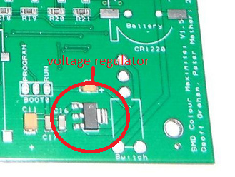 Cut the old one off, and replace. I'm sure Ricetech can advise what part to use. If you can program the board, the cpu should have survived. Hopefully. Regards Womble Edited 2020-10-29 09:47 by Womble |
||||
| TassyJim Guru Joined: 07/08/2011 Location: AustraliaPosts: 6538 |
In your first post, you said that you were able to flash the firmware OK. This would suggest that you are using an A-A cable and when you did, the voltages were OK. You either have a fault overloading the 5V which would also occur with the A-A cable so not likely, or you have a fault in the supply side when using A-B cables. There is only the power switch between the two so look for a different A-B cable. But first, measure the voltages again when using the A-A cable. Jim VK7JH MMedit |
||||
| TassyJim Guru Joined: 07/08/2011 Location: AustraliaPosts: 6538 |
I thought I would write a beginners fault finding guide. The power circuit of the CMM2 is reasonably simple. 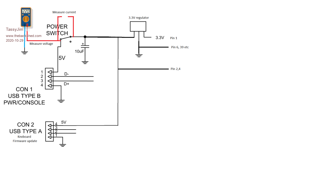 The easiest place to measure voltages is at the power switch. 1. With the switch OFF, measure from the centre pin to ground. My system reads 5.17V but the actual voltage is not too important yet. 2. Switch the unit on and re-measure the voltage to ground. My system with a good cable reads 5.04 Volts With a 'bad' USB cable (actually 5 2M extension leads inserted in series) reads 4.52 Volts with the unit switched on vs 5.17 with the unit switched off. My unit still runs happily at 4.52 Volts but some keyboards may spit the dummy. 3. with the power switch off and the multimeter set to current, measure the units load by putting the leads across the power switch pins. It's the centre pin and the rear pin that we want. My unit reads 270mA with a few external devices still connected. Without the extras, the current is ~200mA Anything under 150mA or over 250mA with no keyboard or connections to the 40 way connector would require investigation. Doing some maths. With the good USB cable there is 5.17-5.04 volts drop in the cable and 270 mA load gives (5.17-5.04)*0.27 = 0.035 ohms lead and power supply impedance. With the 'bad' USB lead (5.17-4.52)*0.27 = 0.175 ohms That doesn't seem much but I would be concerned with that much lead resistance. While I don't have any bad USB cables (as far as I know), I did have some very bad Dupont leads I use on the breadboards. They went into the bin... Jim VK7JH MMedit |
||||
| robert.rozee Guru Joined: 31/12/2012 Location: New ZealandPosts: 2529 |
good idea jim. one point for beginners to point out, is that the shell of the USB keyboard connector is a good ground point to use for making voltage measurements. cheers, rob :-) |
||||
| yock1960 Senior Member Joined: 18/08/2020 Location: United StatesPosts: 167 |
This is what I need...good stuff! Thanks for the help TassyJim and all! Switch off = 5.08V Switch on = 2.25V Above measured as you described. I get no readings for current on any setting. I'm not sure I've ever used this meter (DVM830L) to check current, so I'm not sure it works, although voltage and resistance checks seem okay. Checking voltages at the various legs of the regulator, with power on are: a b c | | | ----- ||| d a = 2.26v b = .68v c = 2.62v d = .68v I've checked with three different cables and from a dedicated USB power jack to a laptop USB port with essentially the same results. To reiterate, the unit connects/reads/flashes in it's current state using the Cube Programmer, but will not connect via serial/console...does not show as a com port in device manager. There are no markings on the top side of the regulator and while I could probably get it off, getting a new one back on in working condition...with my horrid soldering skills is problematic....but what have I got to lose! :-) Steve Steve |
||||
Grogster Admin Group Joined: 31/12/2012 Location: New ZealandPosts: 9975 |
CMM2 must be powered from 5v, and a regulated 5v at that. ĀSome of those 5v USB chargers put out 9v(as mentioned), and some output 5v, but that 5v can also be quite "Dirty", as many of them are very cheap. The regulator is an LM1117-33, and is good for up to 15v input, so even a 9v input should not really have killed it. Yes, something has been cooked. ĀYou should have 5v between pin-2 and ground, and you should have 3v3 between pin-1 and ground. You may have killed C5 or C11, which I think are rated to only 6v3, so putting 9v on them could have made them go short-circuit. With the power switch on the front OFF(up), plug in the 5v, and measure the voltage between ground and the power-switch legs - should be 5v. ĀTurn on the unit and measure the 5v voltage again across the switch and ground. ĀIf it has dropped down to 2v or so, you probably have shorted C5 due to over-voltage. ĀTurn off the switch, remove C5, repeat. ĀIf the voltage now stays at 5v with the switch on(down), then replace C5. EDIT: You've cooked C5. Replace. EDIT: Completely understandable, if C5 is short-circuit. It will be pulling the input voltage right down to 2.26v input, for a regulator that is trying to output 3v3, so you only see a fraction of that on the regulator output, cos the input is now well below the LDO for the wanted output voltage. A is the regulator input - should be 5v B is the regulator output - should be 3v3 C is the regulator ground D is also the regulator output - should be 3v3 Edited 2020-10-29 22:33 by Grogster Smoke makes things work. When the smoke gets out, it stops! |
||||
| Womble Senior Member Joined: 09/07/2020 Location: United KingdomPosts: 267 |
Steve ... On the assumption that you dont have a hot air rework station, two soldering irons, one in each hand should do the trick to remove C5. \_cap_/ like chopsticks  Note that C5 is polarised (looks like a tantalum to my untrained eye), you could probably dead-bug a suitable through hole cap if you don't have a suitable surface mount part. As you mentioned, you have nothing to lose by attempting a repair, and save on the shipping time for a replacement CMM2. Regards Womble |
||||
| twofingers Guru Joined: 02/06/2014 Location: GermanyPosts: 1761 |
i like Grogster's analysis.  @Grogster Is the schematic and a parts list available or is it somehow secret/copyrighted? It could help in cases like this. Thanks! Regards Michael causality ŌēĀ correlation ŌēĀ coincidence |
||||
| yock1960 Senior Member Joined: 18/08/2020 Location: United StatesPosts: 167 |
Dead bug? You mean lay it down flat? Well, since I'm only a DIY'er when necessity requires, I have no capacitors on hand. I can manage the two irons...recent activity reveals I need something a bit better and one that I have should suffice for the other. Possibly the cap is isolated enough for me not to botch anything else! There is one local store that caters to DIY/makers...whether they have anything appropriate is another question. I still need help with identifying a replacement...SMD or not.  Steve (the destroyer) |
||||
| Womble Senior Member Joined: 09/07/2020 Location: United KingdomPosts: 267 |
Michael ... I could not find the schematic or BOM for the v1.5 prebuilt CMM2 on Geoffs site. Probably for copyright reasons, and to protect the commercial investment of the Devs who put in all the hard work bringing us the excellent CMM2 prebuilt. The Waveshare Kit version schematics and BOM are in the CMM2_Construction_Pack.zip which is freely available. There exists an unofficial German clone version here which should have a similar Bill of Materials. this has an easily readable BOM. Regards Womble |
||||
| twofingers Guru Joined: 02/06/2014 Location: GermanyPosts: 1761 |
Thank you. I didn't find anything on Grogster's side either. I just want confirmation that the schematic is not available. I think it would be useful to be able to help or to help yourself. Michael causality ŌēĀ correlation ŌēĀ coincidence |
||||
| matherp Guru Joined: 11/12/2012 Location: United KingdomPosts: 11516 |
All details including gerbers are available on TBS. I've posted them at least twice. Rictech and micromite.org and BigMik all use my design as did CG for his first boards. |
||||
| Womble Senior Member Joined: 09/07/2020 Location: United KingdomPosts: 267 |
Found Them posted way before I knew the CMM2 even existed. Also MainvoardV1.5.zip Edited 2020-10-30 00:51 by Womble |
||||
| Page 1 of 4 |
|||||
| The Back Shed's forum code is written, and hosted, in Australia. | © JAQ Software 2026 |
