
|
|
Forum Index : Microcontroller and PC projects : CMM2: Oscillator Mode is AWESOME.
| Author | Message | ||||
| vegipete Guru Joined: 29/01/2013 Location: CanadaPosts: 1129 |
A big thanks to Peter Mather for making it possible! I recently got around to performing the oscillator modification for my Waveshare boards. The different VGA output modes are now completely steady and completely usable. Before, many modes and resolutions were very disappointing due to tearing, glitching and interference but not any more. Here is a photo of the change. I removed the existing crystal from the other side of the board and dead bugged the replacement oscillator as shown. A 0.1uF 1206 SMD capacitor fits on top. For completeness, the recommended oscillator part number is LFSPXO018045, although there are numerous equivalents out there. (The switches in the photo are set for firmware update mode, not normal run mode.) 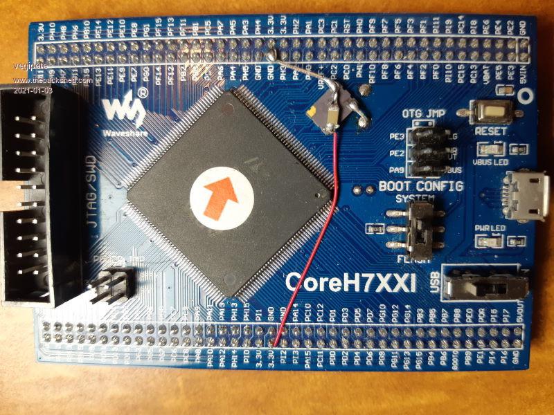 It doesn't look like it but there is lots of clearance between the ground lead and pin PH3. I used clipped LED pins for the rigid connections, wire wrap wire for the 3.3V connection. Visit Vegipete's *Mite Library for cool programs. |
||||
Grogster Admin Group Joined: 31/12/2012 Location: New ZealandPosts: 9592 |
I remember when we were talking about this in the development group, and I for one was really staggered that the crystal oscillator was not stable. You'd think that a crystal(genuine one!) is about as stable as you'd ever get, but it was off/varied just enough to cause timing issues with the VGA, resulting in video artefacts. It did not matter for anything else, just the VGA output. Amazing. Since Peter designed the all-in-one PCB with the OSC pack instead of a discrete crystal + load-caps, the CMM2 video output has been rock-solid. I just plugged in my early prototype made from the Waveshare module based idea, and yeah - I can see all those video artefacts again.  Smoke makes things work. When the smoke gets out, it stops! |
||||
| vegipete Guru Joined: 29/01/2013 Location: CanadaPosts: 1129 |
As I understand it, it is not that the crystal isn't stable. The problem is that the crystal output signal is quite weak and signals on neighbouring tracks can cause interference on the crystal tracks. This is a fault of the Waveshare board designers - they should have minimized the length of and isolated the tracks from the crystal to the MCU. The oscillator fixes the problem because the output signal is much stronger and over-powers the interference. Visit Vegipete's *Mite Library for cool programs. |
||||
| William Leue Guru Joined: 03/07/2020 Location: United StatesPosts: 405 |
I wonder if this fix is relevant for units where the ARM chip is integral with the MOBO and no plugin board is used. Probably not. -Bill |
||||
TassyJim Guru Joined: 07/08/2011 Location: AustraliaPosts: 6269 |
No The all-in-one units already use the good oscillator module. Jim VK7JH MMedit |
||||
| LeoNicolas Guru Joined: 07/10/2020 Location: CanadaPosts: 503 |
This mod solved all my problems related to VGA sync. 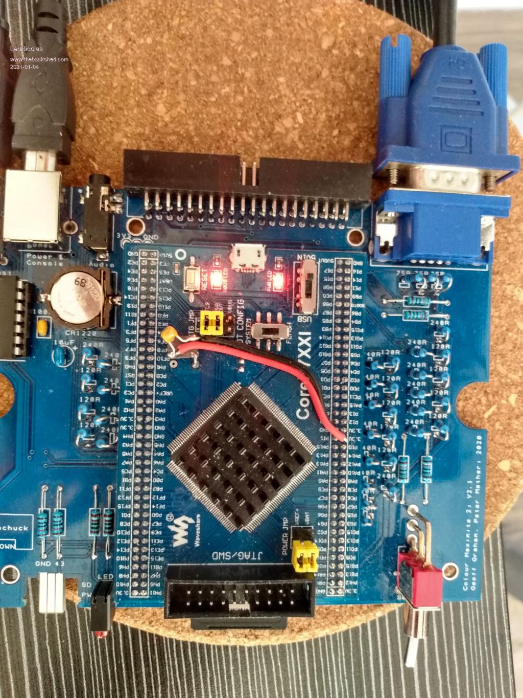 |
||||
| fasd34 Newbie Joined: 04/04/2021 Location: AustraliaPosts: 6 |
Hi, This is quite helpful. I've been struggling getting it to work using the pads on the MM2 board itself, but I see everyone has been putting the new oscillator on the Waveshare board instead. Has anyone used the pads on the MM2 board - I'm starting to think that I'm inadvertently grounding the clock output - solder is bridging over the pad onto the top of the SMD, thus grounding it (??). 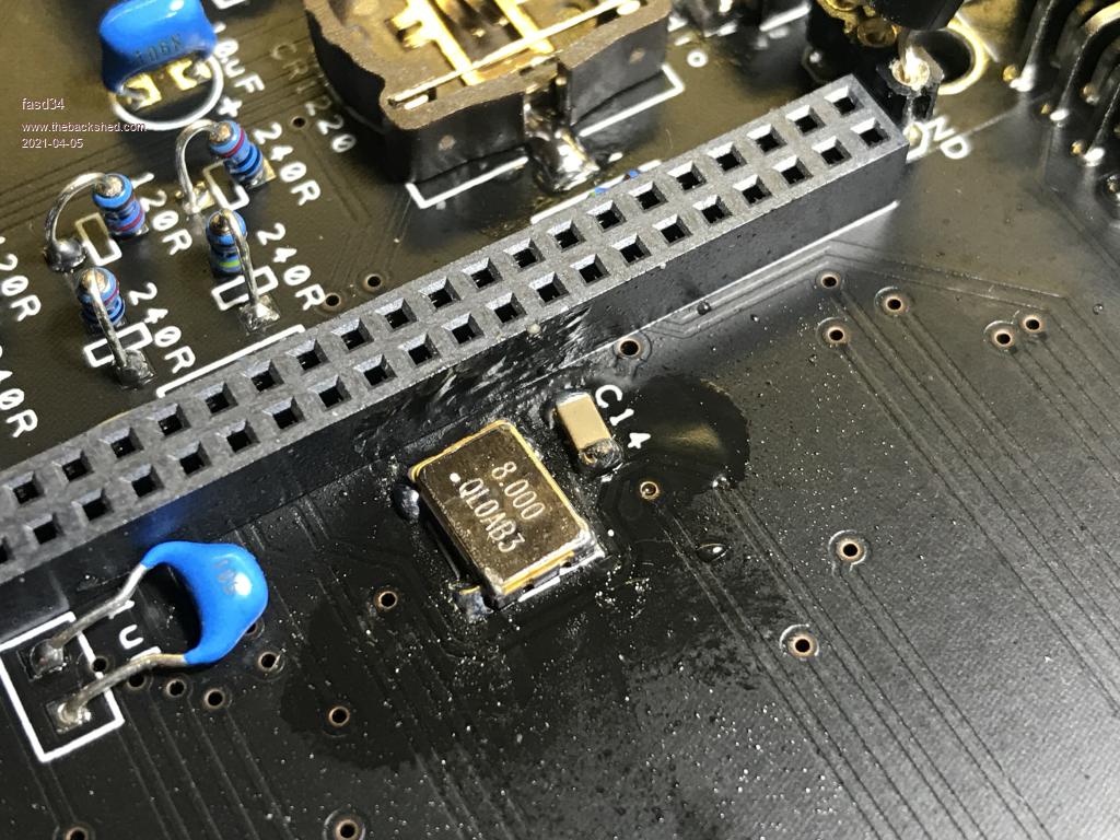 I'm also wondering whether I should de-solder the DIL socket first to make it easier to solder in the capacitor & oscillator. (Please ignore the solder paste gunk). /Brett Edited 2021-04-05 18:04 by fasd34 |
||||
| matherp Guru Joined: 11/12/2012 Location: United KingdomPosts: 10233 |
Brett What tools do you have? If you have a hot air gun with a small nozzle then use it to de-solder the oscillator. Clean up all the solder on the oscillator and PCB using solder wick. Then put a tiny amount of solder on the pads on the PCB. Position the oscillator and then play the hot air on it until it sits into the solder. Takes longer to write than to do. You mustn't bridge between the oscillator case and the pads which looks like it may be the problem. Trying to remove the 40-pin header is a recipe for disaster Edited 2021-04-05 18:23 by matherp |
||||
| Mixtel90 Guru Joined: 05/10/2019 Location: United KingdomPosts: 7858 |
I fitted it on the board ok. It wasn't particularly easy with the waveshare socket in place, but it went in. :) You need an iron with a very fine tip and a decent temperature. I tried a 8W USB soldering iron with a very fine tip and that was more or less ok with plenty of liquid flux. A bigger temp controlled iron was a lot better but I couldn't get it in next to the socket, even though the tip is pretty fine. Overall it's a *vast* improvement. Most of the video modes were more or less unusable until I did the mod. Mick Zilog Inside! nascom.info for Nascom & Gemini Preliminary MMBasic docs & my PCB designs |
||||
| fasd34 Newbie Joined: 04/04/2021 Location: AustraliaPosts: 6 |
I've got pretty much everything I need - fine-tipped iron, vacuum de-soldering gun, hot air gun, solder flux. I'd tried three times now ... with the DIL socket in the way ... so was losing faith that it actually worked, and then I saw this thread where the replacement was done on the Waveshare board itself. But what you have suggested sounds like the best path forward so will try that. I was going off the Silicon Chip instructions which had it listed as an optional after-thought that shouldn't be required for most people, hence why I'm trying to retrofit it in after the DIL sockets. /Brett Edited 2021-04-05 20:26 by fasd34 |
||||
| robert.rozee Guru Joined: 31/12/2012 Location: New ZealandPosts: 2436 |
if using hot air, place a piece of metal sheet between the 40-pin header and the crystal to prevent the hot air melting the plastic header. a piece cut from an aluminium soda can would be ideal, around 2" x 1". bend into a 2" long 'U' shaped channel so it sits over the header and stays in place, and use a piece of paper (folded similarly) between the inside of the aluminium sheet and the header as an additional heat insulator. it does strike me that dead-ant'ing the oscillator module on top of the waveshare board is the far easier approach. i think that 3v3 and ground can possibly be picked up closer by, on the BOOT switch: 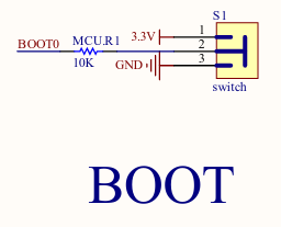 use the 0.1uF capacitor leads to attach the oscillator module to the 3v3 and ground pads of the switch - this will provide good mounting too - and a single short jumper wire to connect the oscillator output. NOTE: i have not tried the above, i don't even own a CMM2. cheers, rob :-) Edited 2021-04-05 20:29 by robert.rozee |
||||
| fasd34 Newbie Joined: 04/04/2021 Location: AustraliaPosts: 6 |
Tried putting it on the MM2 board again, pre-soldering the pads and then hot-air gun but still no luck. So tried putting it on the Waveshare board again, making sure not to ground the oscillator output pin to the ground/top case ... and success finally! First attempt, so a bit ugly. Will stick some Kapton tape underneath this one and make the next one a little neater. /Brett 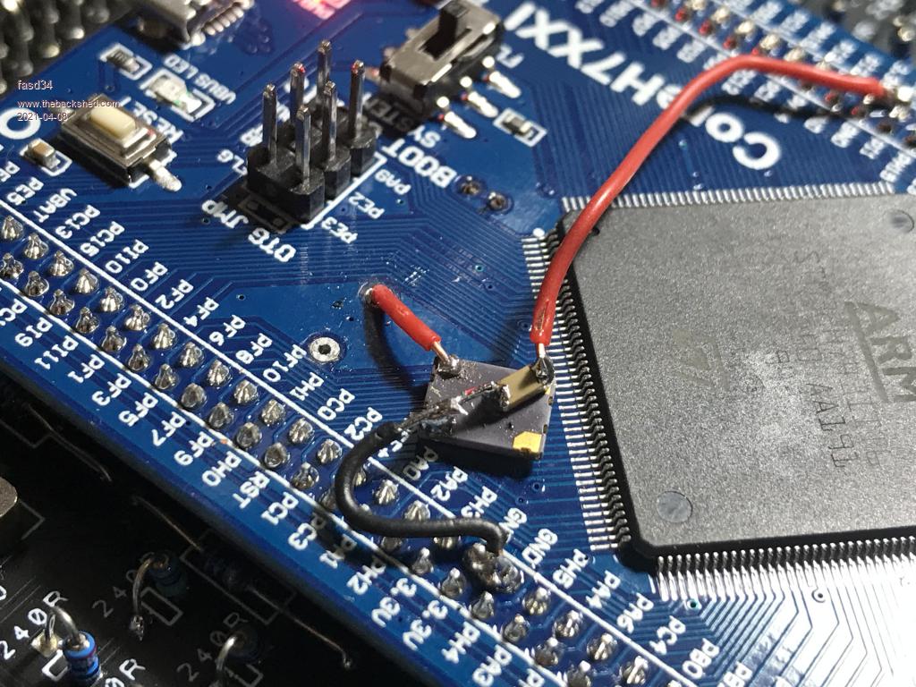 |
||||
| matherp Guru Joined: 11/12/2012 Location: United KingdomPosts: 10233 |
Just looked again at your original photo and the oscillator was upside down. Pin 1 is the dot on the PCB to the right and below the capacitor. Anyway, glad its now working but for next time .... |
||||
| fasd34 Newbie Joined: 04/04/2021 Location: AustraliaPosts: 6 |
HA HA HA HA! Of course! I didn't even bother checking the orientation. First time using these SM versions. ... although, in my defence ... all four pads on the MM2 board are identical (to my eyes), there's no info in the SC articles or schematic, so I simply matched the orientation of the lettering on the board "Y3" with the oscillator! All a learning experience ;) I got the orientation correct when putting it on the Waveshare board as I followed the photos and noticed one pin had an angled cut so made sure I matched it. Second attempt, much neater. /Brett 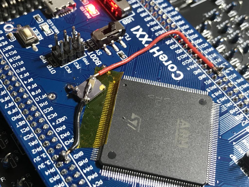 |
||||
| fasd34 Newbie Joined: 04/04/2021 Location: AustraliaPosts: 6 |
Success! Now that I'm wearing my glasses ... and using a loupe ... I can see a tiny white dot on the MM2 board that I should've matched up with the dot on the oscillator case. Duh! Tried again pre-soldering then hot-air gun (little too much solder) ... and it's working! Thanks for pointing that out! Now to try to remove my previous attempts from the other boards :( /Brett 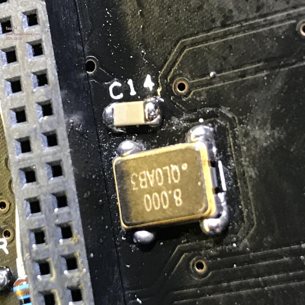 |
||||
| Mixtel90 Guru Joined: 05/10/2019 Location: United KingdomPosts: 7858 |
That white dot isn't that easy to see even when you know about it. Not for my ancient Mk.1 eyeballs anyway. The SMD components don't oblige by making themselves easy to hand solder either. :( Mick Zilog Inside! nascom.info for Nascom & Gemini Preliminary MMBasic docs & my PCB designs |
||||
| fasd34 Newbie Joined: 04/04/2021 Location: AustraliaPosts: 6 |
Indeed! If I have another go at building these, I'll try to tweak the Gerber files first to increase that dot size ;) Probably would've been easier to solder the oscillator on before the 80-pin header, but I'm actually getting pretty adept at using the hot-air gun to de-solder my earlier upside-down attempts, then re-solder the correct way around. Although, mounting the bodge on the Waveshare board gives it that "home-brew" type of nostalgia feel! That little SMD can sure take a lot of heat! /Brett |
||||
| The Back Shed's forum code is written, and hosted, in Australia. | © JAQ Software 2025 |
