
|
|
Forum Index : Microcontroller and PC projects : wiring up a mouse to the CMM2
| Author | Message | ||||
| johngill Newbie Joined: 22/09/2020 Location: United KingdomPosts: 38 |
Hi all, I'd like to have a crack at attaching a PS2 mouse to my CMM2. My soldering skills are adequate, but my electronics understanding is, limited, shall we say! I've found a pin-out of the PS2 connector: 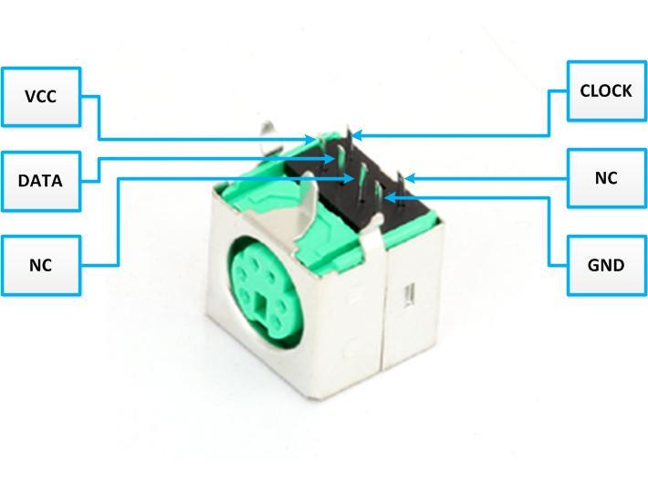 I understand the I/O connector pin out on page 10 of the user guide, and I need to wire up the appropriate pins to the PS2 connector as per the instructions in the readme file on the latest firmware beta download. "To make the connection the MOUSE clock line is connected to pin 33 of the CMM2 and the MOUSE data to pin 32. Both lines MUST be pulled up to 5V with 4K7 resistors" I can understand a circuit diagram, but I don't understand electronics enough to know how the sentence "both lines MUST be pulled up to 5V with 4k7 resistors" translates into a circuit diagram - please can anyone help me? Also, there is a VCC pin on the PS2 connector, which I'm assuming should be connected to +ve power, but there are 2 different voltages on the I/O connector, 3.3V and 5V - I'm guessing I should be using the 5V - is that right? Many thanks in advance |
||||
| matherp Guru Joined: 11/12/2012 Location: United KingdomPosts: 11598 |
Connect a 4K7 resistor between CLOCK and VCC and another between DATA and VCC Yes |
||||
| RetroJoe Senior Member Joined: 06/08/2020 Location: CanadaPosts: 290 |
@johngill, please have a look here It should be obvious from the schematic why they are called pull "up" resistors :) P.S. is your forum name a Star Trek reference ? Edited 2021-02-16 00:46 by RetroJoe Enjoy Every Sandwich / Joe P. |
||||
| RetroJoe Senior Member Joined: 06/08/2020 Location: CanadaPosts: 290 |
These pinouts are unlikely to change, so for future reference (and possible inclusion in the CMM2 docs?), here 'tis the mouse circuit in bitmapped goodness. But, a "live" cloud-based repo of CMM2 circuits contributed by the community remains intriguing :) 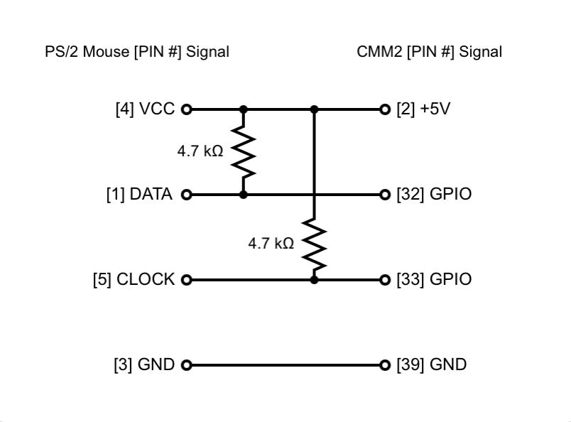 Enjoy Every Sandwich / Joe P. |
||||
| phil99 Guru Joined: 11/02/2018 Location: AustraliaPosts: 3308 |
The top photo has Vcc and Gnd reversed, compared to my MM+ which has ben in use for several years without problem. Please doublecheck this before powering up. Checked further, Vcc and Gnd should be swapped or the keyboard may be damaged. Edited 2021-02-16 16:04 by phil99 |
||||
| paceman Guru Joined: 07/10/2011 Location: AustraliaPosts: 1329 |
I agree that @phill99's post above is correct - the diagram at the top has 5v and Gnd reversed. Greg |
||||
| johngill Newbie Joined: 22/09/2020 Location: United KingdomPosts: 38 |
Many thanks for this - much appreciated - seems one can't rely on google images for good electronics tips - who'd have thought?!   |
||||
| johngill Newbie Joined: 22/09/2020 Location: United KingdomPosts: 38 |
Many thanks for the circuit diagram - very helpful. P.S. I'm John Gill in real life - I do apologise most profusely for breaking the Prime Directive on Ekos!!  |
||||
| The Back Shed's forum code is written, and hosted, in Australia. | © JAQ Software 2026 |
