
|
|
Forum Index : Microcontroller and PC projects : CMM2 Build - SD Card
| Author | Message | ||||
| JonathanWo Newbie Joined: 19/02/2021 Location: United KingdomPosts: 12 |
Hi All, First off I tried searching for the issue and couldn't see anything. I have built the CMM2 kit (  ) and Flashed it with 5.6 - Thanks Geoff for making this possible. ) and Flashed it with 5.6 - Thanks Geoff for making this possible.I have got everything powered on, and surprise surprise, it boots (I say so because it's my first project of this sort of size in a long long time. and now to the BUT in my story. I thought at the time It was fairly difficult to solder the sd card slot on (never done SM components but all seemed to be OK. I checked over my soldering with a magnifying glass (eyes are no way what they were!) all look OK. When I boot I get a message at the bottom of the screen in Red text "A:/ | Check Disk | Date and Time"  I formatted a couple of SD Cards SanDisk and no name - fat32 and copied defender game on to it (this will be such a blast from the past) - but if I try to list files - a get SD Card not found - Thus assuming I have possibly stuffed the slot. Anyone got any pointers on how I can diagnose and hopefully fix this? Much appreciated Jonathan |
||||
| JonathanWo Newbie Joined: 19/02/2021 Location: United KingdomPosts: 12 |
Something I have just also noticed that might be an issue is that the SD light keeps flashing and interrupting the keyboard, so seems I probably have stuffed something along the way. Checked the joints with magnifying glass again and can't spot anything. |
||||
| JonathanWo Newbie Joined: 19/02/2021 Location: United KingdomPosts: 12 |
ok - on a much closer look, I wonder if I knackered a contact  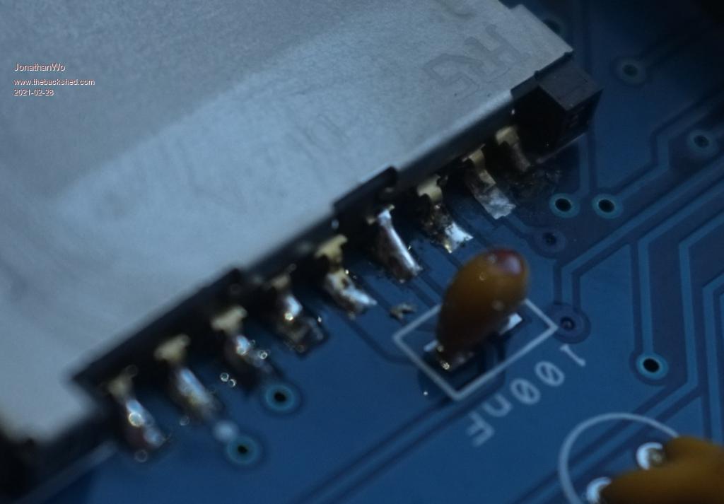 if it is that can I do anything to fix it? Contact most right on the image? Jonathan Edited 2021-02-28 00:48 by JonathanWo |
||||
| matherp Guru Joined: 11/12/2012 Location: United KingdomPosts: 10250 |
No connection to that pin so no issue. The pin next to it looks dry though. Check the very small pins on the side of the socket. Make sure these aren't shorted to the case. "Check disk" means that the firmware isn't seeing the SDcard so you need to find and fix the connections |
||||
| JonathanWo Newbie Joined: 19/02/2021 Location: United KingdomPosts: 12 |
You know what I think in trying to sort that I have made it worse - well not worse, but stuffed the pad Oh well order in to TheWizard for a built kit this time - hahahahha |
||||
| Nelno Regular Member Joined: 22/01/2021 Location: United StatesPosts: 59 |
So, I accidentally knocked the SD card off of my Retromax CMM2, uh... several times while testing my case, so I have a little experience here. Note that the Retromax uses a micro SD card, so it's a little bit different but: Find a reference for SD card connectors. I used this as a reference for Micro SD when I was trying to figure out what I did wrong, but I believe it covers both: https://www.mouser.com/catalog/specsheets/an10911.pdf Also, I agree with what matherp said -- looks like a dry pin there. If you're testing continuity with a multimeter, make sure you're testing from the top of the pin/solder to some end point of the trace. I actually thought I was doing this but the pins were so tiny that I was actually touching the pad under the pin instead of the solder/pin on top. Also, for the micro SD card, the actual pads are connected to ground and these are used to determine when the card is inserted. In the micro SD connectors I have, the insertion pushes an internal pin into the side of the case which completes the connection. This means that even if you have all of the pins connected, you may still need to have the case connected to ground for the card to be detected. I don't know if non-micro SD card connectors use the case for ground, nor do I know if all micro SD card connectors use that same mechanism since in my searches I found quite a number of micro SD card connector variations that seemed to have different latching mechanisms. Those were the two main problems I had. |
||||
| JonathanWo Newbie Joined: 19/02/2021 Location: United KingdomPosts: 12 |
@Nelno, thanks for that. I do need to get a multimeter :( - as I said I seemingly knackered the track on the motherboard when I was trying to sort this. I have got the SD card reader off completely now, and without it I am still seeing the activity light (call) regularly that's interrupting keyboard input, so I am unsure if I have made a mess elsewhere also. I have put it to one side for now (But have ordered a complete build, as I suspect that I will need to spend a bit of time patching the one I built but don't have the skills I feel to tackle that, so I am ordering a replacement SD Card reader and I will then try rig the stuffed traces with wire to where they should be. Multimeter on order also. JW |
||||
| Nelno Regular Member Joined: 22/01/2021 Location: United StatesPosts: 59 |
After several cycles of replacing mine I had delaminated the pads on my board. I made several attempts at replacing the pads using specialized high-temperature epoxy made for PCBs, but they would just delaminate again when I added heat, even after extensive cleaning of the pad sites and with the temperature as low as I could have it and still melt solder. Ultimately I ended up using a patch wire from the case to ground as well as hot glue to secure the card connector. In the process of all of this I also messed up one of the traces, but I fixed that with some very small wire (extracted from 22 gauge braided wire) soldered into the trace. There are lots of great videos on YouTube showing how to do trace repair. It's not too hard as long as you have some magnification, tweezers and some patience. I'm lacking in the patience part. As for the keyboard issue... what's your power supply's amperage? I had trouble with my keyboard working when I was using a 500 mA charger. Once I swapped that out for a 2000 mA charger all of my keyboard issues went away. -Jonathan |
||||
| JonathanWo Newbie Joined: 19/02/2021 Location: United KingdomPosts: 12 |
Hmm, good point on the Amps I think it's 1000mA, will have to do at least 1 trace repair. I'll have to see - I am still peeved at myself :| |
||||
| The Back Shed's forum code is written, and hosted, in Australia. | © JAQ Software 2025 |
