
|
|
Forum Index : Microcontroller and PC projects : CMM2 GPIO pins
| Author | Message | ||||
| lizby Guru Joined: 17/05/2016 Location: United StatesPosts: 3742 |
If it's been posted, I didn't note it. I'm looking for a chart or spreadsheet listing the GPIO pin names and/or numbers for the 20x2 40-pin GPIO connector. Something which supplements these: 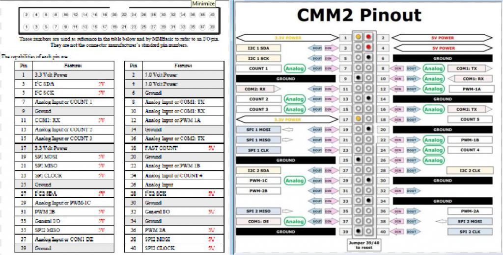 I'm trying to replicate something like what I'm using for a GPIO PCB for the F4: 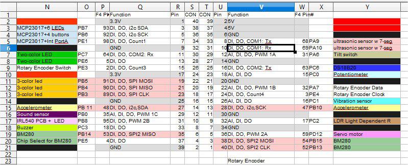 I have a vague recollection that something like this has been posted, but I can't find it. PicoMite, Armmite F4, SensorKits, MMBasic Hardware, Games, etc. on FOTS |
||||
| Turbo46 Guru Joined: 24/12/2017 Location: AustraliaPosts: 1691 |
I posted this during the discussion on joysticks. I can upload it as a doc or spreadsheet if it is of any use? 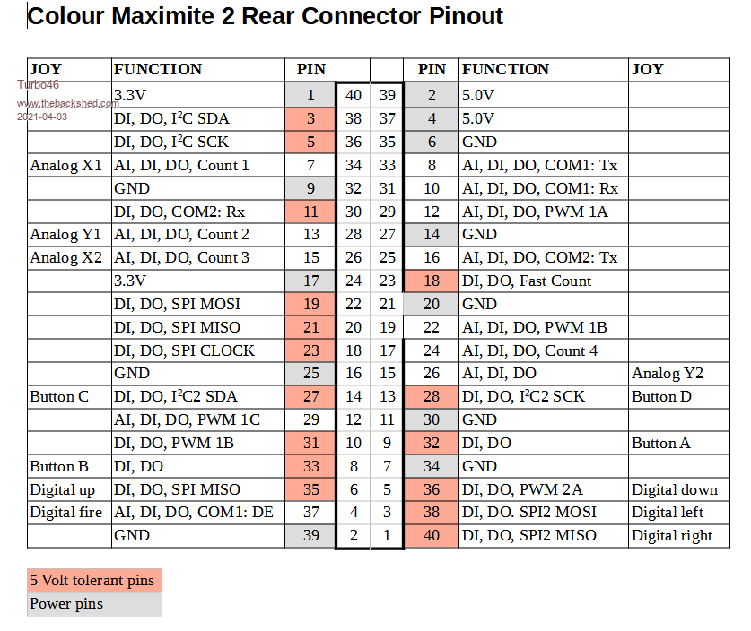 Bill Keep safe. Live long and prosper. |
||||
| matherp Guru Joined: 11/12/2012 Location: United KingdomPosts: 11224 |
This is the master const struct s_PinDef PinDef40[NBRPINS+1]={ { NULL, 0, PUNUSED , NULL, 0}, // pin 0 { NULL, 0, PUNUSED , NULL, 0}, // pin 1 3V3 { NULL, 0, PUNUSED , NULL, 0}, // pin 2 5V { GPIOB, GPIO_PIN_9, DIGITAL_IN | DIGITAL_OUT , NULL, 0}, // pin 3 I2C-SDA { NULL, 0, PUNUSED , NULL, 0}, // pin 4 5V { GPIOB, GPIO_PIN_8, DIGITAL_IN | DIGITAL_OUT , NULL, 0}, // pin 5 I2C-SCK { NULL, 0, PUNUSED , NULL, 0}, // pin 6 GND { GPIOC, GPIO_PIN_1, DIGITAL_IN | DIGITAL_OUT | ANALOG_IN , ADC1, ADC_CHANNEL_11}, // pin 7 COUNT1 { GPIOA, GPIO_PIN_2, DIGITAL_IN | DIGITAL_OUT | ANALOG_IN , ADC2, ADC_CHANNEL_14}, // pin 8 COM1-TX { NULL, 0, PUNUSED , NULL, 0}, // pin 9 GND { GPIOA, GPIO_PIN_3, DIGITAL_IN | DIGITAL_OUT | ANALOG_IN , ADC1, ADC_CHANNEL_15}, // pin 10 COM1-RX { GPIOH, GPIO_PIN_14, DIGITAL_IN | DIGITAL_OUT , NULL, 0}, // pin 11 COM2-RX { GPIOA, GPIO_PIN_6, DIGITAL_IN | DIGITAL_OUT | ANALOG_IN , ADC2, ADC_CHANNEL_3}, // pin 12 PWM-1A { GPIOC, GPIO_PIN_2, DIGITAL_IN | DIGITAL_OUT | ANALOG_IN , ADC3, ADC_CHANNEL_0}, // pin 13 COUNT2,I2S-SDI { NULL, 0, PUNUSED , NULL, 0}, // pin 14 GND { GPIOC, GPIO_PIN_3, DIGITAL_IN | DIGITAL_OUT | ANALOG_IN , ADC3, ADC_CHANNEL_1}, // pin 15 COUNT3,I2S-SDO { GPIOA, GPIO_PIN_0, DIGITAL_IN | DIGITAL_OUT | ANALOG_IN , ADC1, ADC_CHANNEL_16}, // pin 16 COM2-TX { NULL, 0, PUNUSED , NULL, 0}, // pin 17 3V3 { GPIOA, GPIO_PIN_15, DIGITAL_IN | DIGITAL_OUT , NULL, 0}, // pin 18 COUNT5 - FAST { GPIOB, GPIO_PIN_5, DIGITAL_IN | DIGITAL_OUT , NULL, 0}, // pin 19 SPI-OUT { NULL, 0, PUNUSED , NULL, 0}, // pin 20 GND { GPIOB, GPIO_PIN_4, DIGITAL_IN | DIGITAL_OUT , NULL, 0}, // pin 21 SPI-IN { GPIOA, GPIO_PIN_7, DIGITAL_IN | DIGITAL_OUT | ANALOG_IN , ADC1, ADC_CHANNEL_7}, // pin 22 PWM-1B { GPIOB, GPIO_PIN_3, DIGITAL_IN | DIGITAL_OUT , NULL, 0}, // pin 23 SPI-CLK { GPIOC, GPIO_PIN_4, DIGITAL_IN | DIGITAL_OUT | ANALOG_IN , ADC1, ADC_CHANNEL_4}, // pin 24 COUNT4 { NULL, 0, PUNUSED , NULL, 0}, // pin 25 GND { GPIOC, GPIO_PIN_5, DIGITAL_IN | DIGITAL_OUT | ANALOG_IN , ADC2, ADC_CHANNEL_8}, // pin 26 { GPIOB, GPIO_PIN_7, DIGITAL_IN | DIGITAL_OUT , NULL, 0}, // pin 27 I2C2-SDA { GPIOH, GPIO_PIN_11, DIGITAL_IN | DIGITAL_OUT , NULL, 0}, // pin 28 I2C2-SCK { GPIOB, GPIO_PIN_0, DIGITAL_IN | DIGITAL_OUT | ANALOG_IN , ADC2, ADC_CHANNEL_9}, // pin 29 PWM-1C { NULL, 0, PUNUSED , NULL, 0}, // pin 30 GND { GPIOC, GPIO_PIN_7, DIGITAL_IN | DIGITAL_OUT , NULL, 0}, // pin 31 PWM-2B { GPIOI, GPIO_PIN_8, DIGITAL_IN | DIGITAL_OUT , NULL, 0}, // pin 32 { GPIOI, GPIO_PIN_3, DIGITAL_IN | DIGITAL_OUT , NULL, 0}, // pin 33 { NULL, 0, PUNUSED , NULL, 0}, // pin 34 GND { GPIOB, GPIO_PIN_14, DIGITAL_IN | DIGITAL_OUT , NULL, 0}, // pin 35 SPI2-IN { GPIOC, GPIO_PIN_6, DIGITAL_IN | DIGITAL_OUT , NULL, 0}, // pin 36 PWM-2A { GPIOA, GPIO_PIN_1, DIGITAL_IN | DIGITAL_OUT | ANALOG_IN , ADC1, ADC_CHANNEL_17}, // pin 37 COM1-DE { GPIOB, GPIO_PIN_15, DIGITAL_IN | DIGITAL_OUT , NULL, 0}, // pin 38 SPI2-OUT { NULL, 0, PUNUSED , NULL, 0}, // pin 39 GND { GPIOB, GPIO_PIN_13, DIGITAL_IN | DIGITAL_OUT , NULL, 0}, // pin 40 SPI2-CLK { GPIOB, GPIO_PIN_12, DIGITAL_IN | DIGITAL_OUT , NULL, 0}, // pin 41 IR { GPIOE, GPIO_PIN_2, DIGITAL_IN | DIGITAL_OUT , NULL, 0}, // pin 42 DS18B20 { GPIOB, GPIO_PIN_11, DIGITAL_IN | DIGITAL_OUT , NULL, 0}, // pin 43 Nunchuck SDA { GPIOH, GPIO_PIN_4, DIGITAL_IN | DIGITAL_OUT | ANALOG_IN , ADC3, ADC_CHANNEL_15}, // pin 44 Nunchuck SCK }; |
||||
| lizby Guru Joined: 17/05/2016 Location: United StatesPosts: 3742 |
Thanks, Bill and Peter. I'm pretty sure I had something like Bill's posting in spreadsheet format, and that was what I used to produce the provisional F4 layout, but I can't find it. I2C, SPI, COM1 and COM2 are in the same place, but there were fewer ADC available on the F4, and I don't think I was able to get all the PWMs. I'll use that as a template with Peter's master and will post the spreadsheet doc. Lance PicoMite, Armmite F4, SensorKits, MMBasic Hardware, Games, etc. on FOTS |
||||
| jirsoft Guru Joined: 18/09/2020 Location: Czech RepublicPosts: 533 |
It will be candidate for CMM2.fun entry... Jiri Napoleon Commander and SimplEd for CMM2 (GitHub), CMM2.fun |
||||
| lizby Guru Joined: 17/05/2016 Location: United StatesPosts: 3742 |
Here's a shot of the spreadsheet with the pin names. Since I've been working with the F4, I had forgotten that the CMM2 pin numbers are the same as the 20x2 connector pin numbers. 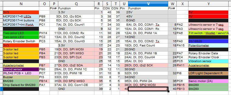 Here's a video of LEDs being lit off of BigMic's 20x2 slim breadboard PCB: CMM2 LEDs Here's the program: ' t_leds.bas dim integer i,j,k,p(15)=(0,3,5,7,11,13,15,19,21,23,27,29,31,33,35,37) ' CMM2 odd row dim p2(13)=(0,8,10,12,16,18,22,24,26,28,32,36,38,40) ' CMM2 even row for i=1 to 15: setpin p(i),dout: next: for i=1 to 13: setpin p2(i),dout: next do for i=1 to 15: pin(p(i))=1: ?p(i);" ";: pause 1000: next for i=1 to 13: pin(p2(i))=1: ?p2(i);" ";: pause 1000: next: for i=1 to 15: pin(p(i))=0: next:for i=1 to 13: pin(p2(i))=0: next loop Pins 37 and 18 are omitted because I ran out of LEDs. 22 LEDs are lit. I haven't yet tried the SPI, I2C, PWM, COM, count, etc. functions. PicoMite, Armmite F4, SensorKits, MMBasic Hardware, Games, etc. on FOTS |
||||
| lizby Guru Joined: 17/05/2016 Location: United StatesPosts: 3742 |
Jiri--I've got a ways to go before I get there, including a re-do of a PCB, but will be happy to post to your site when I have a finished product. PicoMite, Armmite F4, SensorKits, MMBasic Hardware, Games, etc. on FOTS |
||||
| The Back Shed's forum code is written, and hosted, in Australia. | © JAQ Software 2026 |
