
|
|
Forum Index : Microcontroller and PC projects : Can anyone point me at the correct SMD fuse ?
| Page 1 of 2 |
|||||
| Author | Message | ||||
| thwill Guru Joined: 16/09/2019 Location: United KingdomPosts: 4362 |
Hi folks, I'm currently tinkering with (read as "breaking even more like an unskilled chimpanzee") an Amstrad NC 100 notepad about which internal datasheets are somewhat sparse. I need to replace a blown 0.8 amp SMD fuse and I was wondering if anyone could point me in the correct direction of, or make an educated guess as to a suitable replacement - preferably one that I can get without buying in the 100's or paying 10x more in postage than the value of the part: The fuse I've removed - which may not be the original (scale in cm/mm): 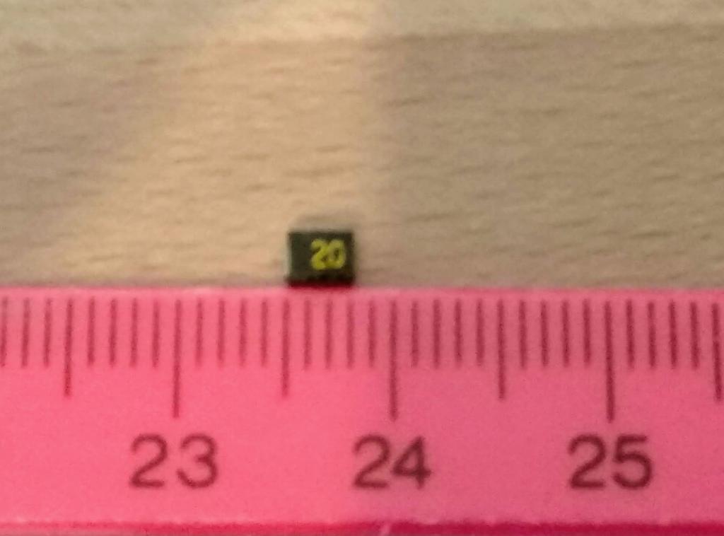 Someone else's fix - with insufficient details: https://gettingby.batsocks.co.uk/2011/05/25/amstrad-nc100-fuse-10/ Thanks in advance, Tom Edited 2021-05-05 20:12 by thwill MMBasic for Linux, Game*Mite, CMM2 Welcome Tape, Creaky old text adventures |
||||
| matherp Guru Joined: 11/12/2012 Location: United KingdomPosts: 11068 |
https://www.ebay.co.uk/itm/114763447921?hash=item1ab86f3e71:g:so8AAOSwsYpaLrCF Basically any 1210 fuse of suitable rating or a 1206 fuse would do equally well Edited 2021-05-05 20:17 by matherp |
||||
| thwill Guru Joined: 16/09/2019 Location: United KingdomPosts: 4362 |
Thanks Peter, and I now know what the Voltage rating of a fuse is for ;-) - if this thing gets 72V from a 6V supply I think there are other problems. In the real world does the difference between 0.8 A and 1.0 A not matter ? Best wishes, Tom MMBasic for Linux, Game*Mite, CMM2 Welcome Tape, Creaky old text adventures |
||||
| matherp Guru Joined: 11/12/2012 Location: United KingdomPosts: 11068 |
Not in my world but others may disagree - See https://www.youtube.com/watch?v=WG11rVcMOnY for more info on what fuse ratings really mean (or don't) |
||||
| Volhout Guru Joined: 05/03/2018 Location: NetherlandsPosts: 5782 |
The fuse value is in most cases optimized to cover possible fault causes. Since the link shows photos from a low voltage dc power inlet, the value of 0.8A is also related to the original adapter provided. If you plan to repace the adapter with a switchmode brick that can supply more current, a value of 1A is perfectly fine. Volhout. PicomiteVGA PETSCII ROBOTS |
||||
| thwill Guru Joined: 16/09/2019 Location: United KingdomPosts: 4362 |
Thanks. Currently I'm trying to power it with 6V from my bench power-supply. The fuse blowing is a known issue with the NC-100 because like a lot of older computers it requires a center-negative power and people accidentally plug in center-positive ones. However I bypassed the fuse and it still isn't working, so probably it is broken beyond my capability, or my unwavering ability to cock up practical DIY has caused me to screw it up further  Nevermind, it only cost pocket-money and is still interesting to poke. Nevermind, it only cost pocket-money and is still interesting to poke.Best wishes, Tom Edited 2021-05-06 04:40 by thwill MMBasic for Linux, Game*Mite, CMM2 Welcome Tape, Creaky old text adventures |
||||
| phil99 Guru Joined: 11/02/2018 Location: AustraliaPosts: 3073 |
As the nominal supply voltage is greater than the logic voltage there must be a regulator in between. If it went open or short to ground you may be in luck. After removing the regulator check the resistance between the main 5V bus and ground. If it's 0 ohms you may still have a chance, one chip may have shorted fast enough to protect everything else. To find the short apply a regulated 1 amp supply to the bus and measure the mV between the supply pins of each chip, starting with the one closest to the supply. The first one along the bus to be near 0 is likely to be shorted. Remove it, check it and continue until you have all the shorted chips removed. If chips have failed open circuit it gets much harder. Sometimes a bulk replacement is quickest, assuming they are all still available. Buying another Amstrad might be cheaper. |
||||
| thwill Guru Joined: 16/09/2019 Location: United KingdomPosts: 4362 |
Thanks for the pointers Phil. So I need to take the regulator out, it can't be checked within the circuit ? Does that mean I need a constant-current bench supply, that would be a problem, mine is only constant voltage. I will probably do that anyway, but that doesn't mean I can't learn from the broken board. At least these things aren't highly sought after by the retro community. So far I've learnt that not having a sense of smell (non-Covid related) may be a severe disadvantage because I can't smell overheating silicon / solder / burning dust. Thanks again, Tom MMBasic for Linux, Game*Mite, CMM2 Welcome Tape, Creaky old text adventures |
||||
| phil99 Guru Joined: 11/02/2018 Location: AustraliaPosts: 3073 |
The regulator can fail in a number of ways, but if you're blowing fuses it's probably dead. Easiest to test it on a breadboard with a load resistor. Your existing supply is fine. Just set your supply to a low voltage (2 to 5V) and put a resistor of equal value in series with the Amstrad 5V bus. Eg 4.7V and 4.7 ohm 5 Watt resistor will give 1A into a short circuit. Edited 2021-05-06 22:56 by phil99 |
||||
| Mixtel90 Guru Joined: 05/10/2019 Location: United KingdomPosts: 8673 |
The NC 100 power supply is 6v 300mA rated, outer +ve. The 6v input feeds a DC/DC converter, giving 6V, 5V & -15v (for the display) A lithium cell provides a 5vBK line, 5v to the CMOS RAM and RTC. I've not been able to find a schematic drawing, but from the above I suspect that the supply is based around a little oscillator near the 6v input. I don't think it will be a simple regulator to 5v because of the age (it would be easy enough with a modern LDO). An oscillator of some sort would be needed for the -15v supply anyway. https://www.cpcwiki.eu/index.php/A_surgical_guide_to_the_Amstrad_NC Mick Zilog Inside! nascom.info for Nascom & Gemini Preliminary MMBasic docs & my PCB designs |
||||
| thwill Guru Joined: 16/09/2019 Location: United KingdomPosts: 4362 |
So the circled device is not a 5V regulator (it has no writing on the visible side) ? 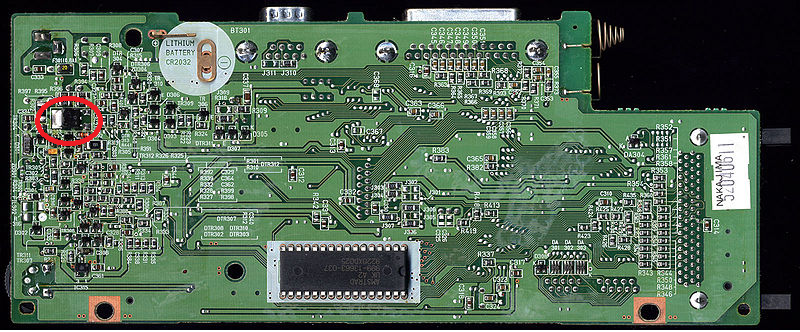 (low-res) images of the board can be found here https://www.cpcwiki.eu/index.php/NC_Series_Mainboard_Versions, I have the NA 999-32141 Board though the arrangement of the bodge on the top-side isn't (cosmetically) identical. Thanks to anyone taking an interest. Given it isn't just the fuse I don't have any great expectations of fixing this myself (I understand my limitations) but I'm still interested in learning whatever I can from it. Best wishes, Tom Edited 2021-05-07 01:26 by thwill MMBasic for Linux, Game*Mite, CMM2 Welcome Tape, Creaky old text adventures |
||||
| Mixtel90 Guru Joined: 05/10/2019 Location: United KingdomPosts: 8673 |
It may well be the 5v reg, Tom. If so it's almost certain to be a low drop out device as 1v drop isn't enough for anything like the 78xx series. Try powering it up at 6v with a 2.7R resistor (although I would prefer a 6v 2W or 4W bulb) in series and checking the pins of the reg to see what voltage is on them. There is a group of four small electrolytics, C319-C322, on the other side. Given the age of the beastie it's worth at least checking those for any bulges. They *might* be a diode pump for the -15v supply but I'm only guessing. (your link to the pics also links to some higher resolution originals, which helps. :) ) Does the NC100 have a "power on" led or is it just the screen? If the latter then losing the -15v might make you think it isn't working. I noticed on one site that someone had used a 200mA fuse, which might be marginal but it shows that the 300mA supply is plenty big enough. Mick Zilog Inside! nascom.info for Nascom & Gemini Preliminary MMBasic docs & my PCB designs |
||||
| thwill Guru Joined: 16/09/2019 Location: United KingdomPosts: 4362 |
Thanks Mick, I'm assuming this is again once it is off the board and that's a 5W resistor (I'm unduly pleased with myself for realising that before ordering a bunch of 1/2 W resistors.) My reluctance to remove it from the board is that I think it's going to be a swine to remove and as things stand currently I could without guilt put this NC-100 back on eBay "for spares or repair", that may not be the case once I've botched the removal and ripped up some of the traces They look fine to me, but this is my first rodeo. There is no power-on LED, but the speaker did "randomly" scream at me. It then stopped and I discovered the cable had come free of the speaker at one end, I'm not sure if that was my carelessness or because it burnt out at that end - hence my comment earlier ruing my lack of sense of smell. I'm sorry, I don't know what that you are trying to say. Best wishes, Tom MMBasic for Linux, Game*Mite, CMM2 Welcome Tape, Creaky old text adventures |
||||
| Mixtel90 Guru Joined: 05/10/2019 Location: United KingdomPosts: 8673 |
On the site that I saw the bloke hadn't got a 800mA fuse but he did have a 200mA so he put that in. The system appeared to work fine. I suspect that the current consumption will be less than 200mA for an unexpanded machine - it might be higher if other things are added. The black blob/regulator soldered down will probably be a right pig to remove. That's why I'd suggest doing everything you can to test it before you consider attempting to remove it. The beauty of using motorbike (and car) bulbs as current limiters is that their cold resistance is low. You don't get as much volt drop as you'll get with a resistor. However, if you have a short the bulb will light brightly and the current will drop to the rating of the bulb. It's pretty neat! Mick Zilog Inside! nascom.info for Nascom & Gemini Preliminary MMBasic docs & my PCB designs |
||||
| Volhout Guru Joined: 05/03/2018 Location: NetherlandsPosts: 5782 |
In stead of trying to make it work with the external powersupply, why don't you first put in 4x AA battery. If it works then you can get to the next step. If it does not work with the AA cells then you have to fix that first. It is possible the AA cells are diode or-ed with the 6V power supply, but I expect a regulator to stabilize to 5V, And that could very well be a discrete regulator. I owned a PX8, that had options to have C cells or a nicad pack. And the regulators (and charger) where discrete build. No LDO. But the PX8 was from 1984 (8 years older than the NC100). Edited 2021-05-08 06:04 by Volhout PicomiteVGA PETSCII ROBOTS |
||||
| Volhout Guru Joined: 05/03/2018 Location: NetherlandsPosts: 5782 |
@Mixtel90: The 800mA fuse is probably very overrated. A 300mA charger cannot blow it. It must also be connected to the AA cells (these can provide enough current). The NC100 according wikipedia can run 20 hours on 4 AA cells, meaning the units draws 100mA-150mA. PicomiteVGA PETSCII ROBOTS |
||||
| Mixtel90 Guru Joined: 05/10/2019 Location: United KingdomPosts: 8673 |
It looks like the AA cells are fed via a switched power socket, not diode switching. The incoming 6v rail then feeds a dc/dc converter, via the 800mA fuse, with a digital enable signal from a flip-flop (IC313A). I can't find any details whatsoever of the dc/dc converter (or any circuits whatsoever in fact) but there doesn't seem to be an inductor, which I would have expected if the 5v rail was to come from there. It could be a discrete LDO reg or even a normal transistor (no number on it?) in either a linear or switching regulator feeding a capacitor. The blob could even be a mosfet used to switch the 6v rail on and there is some sort of regulation elsewhere (there are some little 3-leg SMDs round there). It really needs some voltage measurements as an absolute minimum. Mick Zilog Inside! nascom.info for Nascom & Gemini Preliminary MMBasic docs & my PCB designs |
||||
| thwill Guru Joined: 16/09/2019 Location: United KingdomPosts: 4362 |
Much of this is going over my head, this is a big (some might say foolish) leap from flashing LEDs with a microcontroller and making breakout boards from perfboard. The positive terminals on the battery and on the 6V power socket are directly connected by a broad trace on the top of the board running under the parallel and serial connectors. Sounds like the 1 amp fuses I ordered on flea-bay may be too big to be terribly useful. There is nothing written on the big 3 legged blob that looks like a regulator. If you are interested then I'm happy to take some measurements, but for the moment assume I'm an idiot and give me detailed instructions. I can also try to take some close up video of the board if you think a more detailed "visual" inspection would help. I'm aware that trying to get someone else to remotely diagnose the problem with this board is bordering on the ridiculous so if you think I should just let it go then please let me know. Best wishes, Tom MMBasic for Linux, Game*Mite, CMM2 Welcome Tape, Creaky old text adventures |
||||
| thwill Guru Joined: 16/09/2019 Location: United KingdomPosts: 4362 |
It turns out it was just filthy and a Q-tip and some IPA reveal it thus: 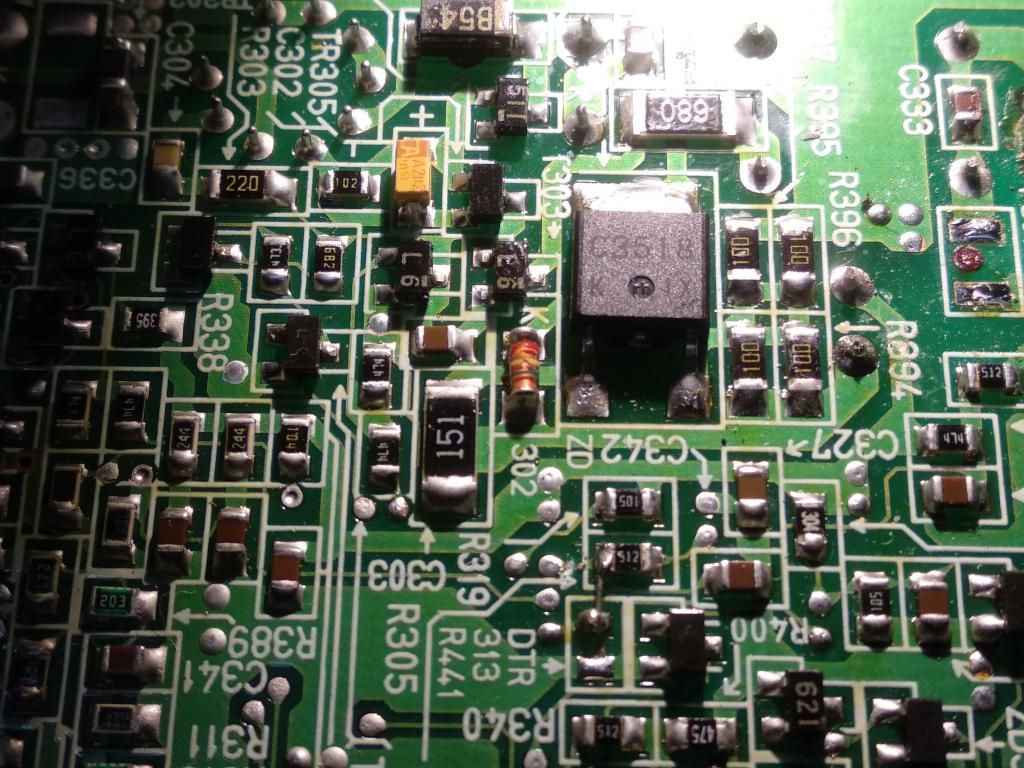 Best wishes, Tom MMBasic for Linux, Game*Mite, CMM2 Welcome Tape, Creaky old text adventures |
||||
| matherp Guru Joined: 11/12/2012 Location: United KingdomPosts: 11068 |
2SC3518 |
||||
| Page 1 of 2 |
|||||
| The Back Shed's forum code is written, and hosted, in Australia. | © JAQ Software 2026 |
