
|
|
Forum Index : Microcontroller and PC projects : MuP F4-Eastrising All in One
| Author | Message | ||||
bigmik Guru Joined: 20/06/2011 Location: AustraliaPosts: 2981 |
Hi All, A fellow user, AndrewG, put me onto the F4 and I must say it is quite impressive. Andrew also twisted my arm to buy a 9" Eastrising TFT and I am speechless. All I can say is "wow what a combination" Andrew showed me his collection of adapters and Vero board Prototypes and I thought that I can help him and possibly others here so I came up with MuP F4-Eastrising. Herein called F4-ER. I think, rather than prattle on I will attach some pictures of the prototype and leave it up to anyone interested to ask questions or comment. All modules are designed to mount on the bottom side of the PCB to allow the `stack' to be relatively thin. I chose a nice Hammond case that fits it perfectly (250mm x 160mm x 40mm external). Top View 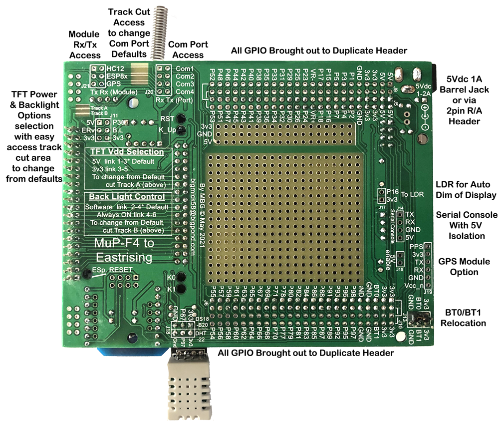 Bottom View 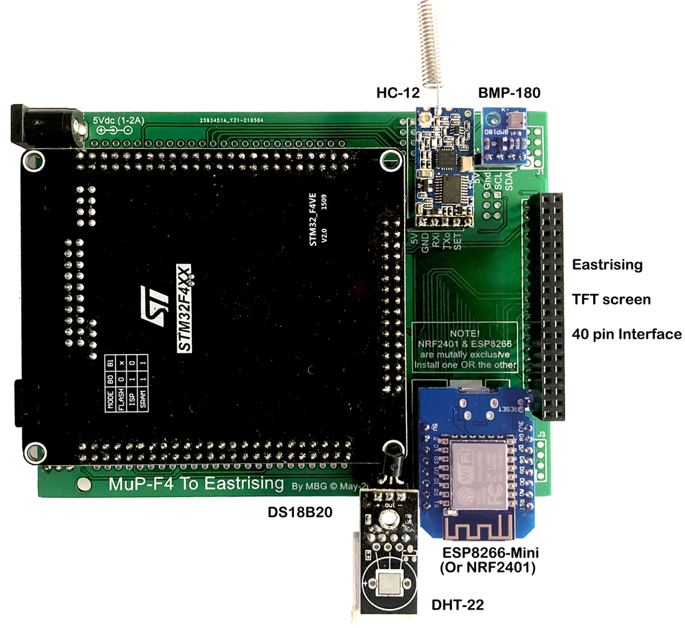 Attached to ER 9" 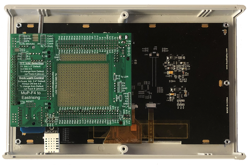 Case Closed 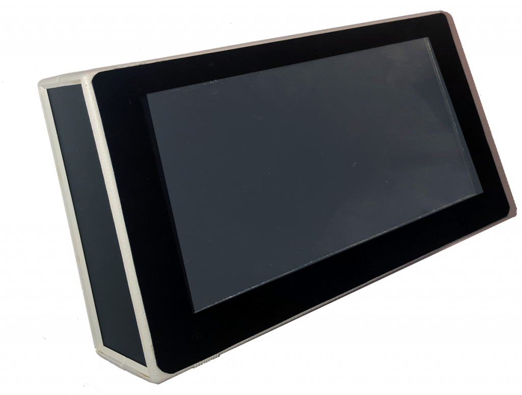 Any Comments or questions? As is usual, there are a couple of minor issues with this first run. The Main issue is 2 pads are erroneously connected to GND but I will drill these pads away and they will have no impact on the PCB. The rest is relatively minor. If anyone is interested I have about 8 or extra boards available for $8AU each plus $1 postage in AUS or $3.50 anywhere overseas. Special Thanks to Geoff Graham, Peter Mather and Andrew Garrett without whom this board would not be here. Kind Regards, Mick Edited 2021-05-15 13:26 by bigmik Mick's uMite Stuff can be found >>> HERE (Kindly hosted by Dontronics) <<< |
||||
OA47 Guru Joined: 11/04/2012 Location: AustraliaPosts: 1050 |
Gday Mick, very interested in a couple of boards. Will organise a PP payment if OK?. All the Best OA47 |
||||
| bigmik Guru Joined: 20/06/2011 Location: AustraliaPosts: 2981 |
Hi Graeme, Certainly just email be at bigmick58@bigpond.com. I have not really started on the manual at the moment, been taking pictures mostly. Most sections have been tested and working OK. We have just discovered that there is more than one pinout for the DHT22 and Andrew's and My modules have different layouts, I designed it to suit my layout.. Most people would want to mount the DHT22 away from the board anyway so it is only 3 wires and can be plugged up as required to suit your module. Also I have the DHT pins in this board powered by 3v3 the next one will go to 5V as that is more in line with the specs, although many state that it works on 3v3. Kind Regards, Mick Mick's uMite Stuff can be found >>> HERE (Kindly hosted by Dontronics) <<< |
||||
| OA47 Guru Joined: 11/04/2012 Location: AustraliaPosts: 1050 |
Hey Mick just noticed your not far away from a 10 year anniversary with TBS. Thank you for all of your contributions. OA47 |
||||
| JohnS Guru Joined: 18/11/2011 Location: United KingdomPosts: 4358 |
Looks good! Please post links for the EastRising 9" John |
||||
| bigmik Guru Joined: 20/06/2011 Location: AustraliaPosts: 2981 |
Hi John, It wasn't cheap when I bought it a month ago, but it has gone UP again.. Grrr >>> ER 9" TFT <<< The SKU: off my order is ER-TFTM090-1-3662-8080-5V-4087-2559 Select: 8080 interface 5V Resistive Touch No need to select uSD interface or Font chips as they aren't used in the current implementation. Not a cheap display but very nice and BIG. Regards, Mick Mick's uMite Stuff can be found >>> HERE (Kindly hosted by Dontronics) <<< |
||||
lew247 Guru Joined: 23/12/2015 Location: United KingdomPosts: 1709 |
Why resistive touch? Is there no way to make MM work with the capacitive touch? |
||||
| RendPhys Newbie Joined: 29/10/2020 Location: NetherlandsPosts: 8 |
Looks nice and as a complete package  |
||||
| JohnS Guru Joined: 18/11/2011 Location: United KingdomPosts: 4358 |
Mick, Thanks - and yes costly :( John |
||||
| bigfix Senior Member Joined: 20/02/2014 Location: AustriaPosts: 132 |
Looks very useful and well designed to me ! There is only one issue - the F4 Module Frontside is not so easy accessible Every unplug/reinsert puts mechanical stress on the F4 module It may be better to install an external battery holder, as was discussed in another thread about option loss Or a fat external Li Battery which will last for the lifetime I am not sure if regular access to other features on the frontside is required ? (Switches, Jumpers, Headers) |
||||
| lizby Guru Joined: 17/05/2016 Location: United StatesPosts: 3837 |
Looks great. I like the ESP8266 D1 Mini connection--the most useful of the ESP8266s IMO. Is the case stock or custom-made? PicoMite, Armmite F4, SensorKits, MMBasic Hardware, Games, etc. on FOTS |
||||
| bigmik Guru Joined: 20/06/2011 Location: AustraliaPosts: 2981 |
Hi All, @Lew, I dont know the reason but PeterM has only ever, the the best of my knowledge, supported Resistive touch screens @RendPhys Thank You. @bigfix Thank You, and no module plugs directly to the F4 board, all modules connect to the 'MuP-F4-EastRising' PCB. There should be no need to access the F4, the USB port and SD card are still accessible (with the rear of the case removed) and the mini switches are all reachable through holes drilled in my F4-ER PCB. If you look carefully in my first image you will see holes drilled for the 4 switches and the ESP reset button. Even the 20way R/A header is accisble without removing the F4. In fact it isnt so easy to actually remove the F4 as there are 2 x 48pin GPIO plus 32pin TFT header Plus 8pin NRF pass through plus 4pin serial console, a total of 140 pins (male/female sets) attaching the F4 to the F4-ER board. I will look at the thread you mention on battery backup (do you have a link??) to see what that is all about, but that may be a user's choice. As to switches as mentioned they are accessible and I have replicated the BT0/BT1 links so you can flash the F4 without removing it. In practice some/most/all modules may be actually installed OFF board (ie externally) for example what is the use of a temperature reading of inside the case unless you actually wish to read the temp inside the case. @lizby, The case is available from Element14 >>> Case <<< and quite cheaply and it looks great. I cut the hole with my dremel and the fascia is actually a thin black plastic cover from a folder that you often get with clear sleeves to insert A4/Letter sheets into. Readilly available and dirt cheap. And looks reasonably good. Kind Regards, Mick Mick's uMite Stuff can be found >>> HERE (Kindly hosted by Dontronics) <<< |
||||
| bigfix Senior Member Joined: 20/02/2014 Location: AustriaPosts: 132 |
Mick, this was the battery discussion: F4 Options storage lost by battery failure It may be best to remove the normal frontside battery and modify the F4 Board with an external battery connection before mounting |
||||
| The Back Shed's forum code is written, and hosted, in Australia. | © JAQ Software 2026 |
