
|
|
Forum Index : Microcontroller and PC projects : Colour Maximite 2 - Second Generation
| Page 1 of 4 |
|||||
| Author | Message | ||||
| Geoffg Guru Joined: 06/06/2011 Location: AustraliaPosts: 3362 |
 The Generation 2 design is fully compatible with the first generation and is primarily designed to be easier to manufacture. This version is not intended to supersede the first generation; it is more of an evolution with a number extra features: - An additional 1920 x 1080 pixel VGA mode. - 24-bit colour output (in addition to the standard 8, 12 and 16-bit modes). - Extra RAM for BASIC programs (24MB vs 8MB). - Support for a USB mouse (with an optional Hobbytronics chip) or a dual USB/PS2 wired mouse (no extra components required). - Two Wii controller ports on the front panel. - Support for an optional high accuracy real time clock (RTC) replacing the standard RTC and an optional ESP-01 WiFi module. Because this design mostly uses surface mount components it is not recommended for home constructors and vendors will be supplying it as either partially or fully assembled. If you are really keen you can build it yourself - the construction pack on my website has the details but you need to be VERY good at surface mount soldering. You can also get a PCB fabricator like JLCPCB to supply and solder the parts for you, the required info is in the construction pack. My website has been updated with the latest firmware and manuals: http://geoffg.net/maximite.html The usual suppliers will be offering the 2nd Generation design (in no particular order): - Rictech in New Zealand: https://www.rictech.nz/micromite-products - Micromite Org in the UK: https://micromite.org - CircuitGizmos in the USA: https://circuitgizmos.com/RetroMax-CGs-Color-Maximite-2-p241231864 - PS Labs in Poland: https://sklep.pslabs.pl/Maximite-c91/s_lang/en Give them a little time to update their websites. As most of you know there is a worldwide shortage of semiconductors and we have seen this with the ARM Cortex-M7 and RAM chips used in this design, so please be kind to your supplier if you experience extended delivery times. Expect to see a two part series in Silicon Chip magazine describing the Generation 2 with the first article to hit the streets towards the end of this month. We are releasing this early so that members of this forum can try out the firmware and report any issues (hopefully there will be none). Congratulations to Peter for another huge effort. Geoff  Geoff Graham - http://geoffg.net |
||||
CircuitGizmos Guru Joined: 08/09/2011 Location: United StatesPosts: 1427 |
Circuit Gizmos has the RetroMax version 2.3a available. Slightly different design from the CMM2 Gen 2 that Peter has made, but compatible with the firmware/software. The RetroMax 2.3a (this is the generation 2 compatible design) is in stock at CircuitGizmos and will be shipping out around the 8th. This can be ordered with or without the "slim" case and other optional items. 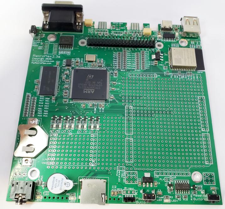 The RetroMax Generation 2 design is fully compatible with the first generation (RetroMax 1.4a), however, it has a few extra features: CMM2 Gen2: - An additional 1920 x 1080 pixel VGA mode. - 24-bit color output (in addition to the standard 8, 12, and 16-bit modes). - Extra RAM for BASIC programs (24MB vs 8MB). - Connections that support a wired PS2 mouse or a combo USB/PS2 wired mouse. - Support for an optional high accuracy real time clock (RTC) on the PCB replacing the standard RTC. RetroMax specific: - Inclusion of an ESP32 WiFi module on the PCB. - A USB "C" Console/Power connection to use better and more stable USB supplies. - Two QWIIC connectors for convenient I2C connections. - Self shutoff feature for the RetroMax. The 1.4a (gen 1) version is also still available. Edited 2021-07-02 12:49 by CircuitGizmos Micromites and Maximites! - Beginning Maximite |
||||
| CircuitGizmos Guru Joined: 08/09/2011 Location: United StatesPosts: 1427 |
To take advantage of the QWIIC interface connectors on the RetroMax 2.3a, the QuickQWIIC is also available: 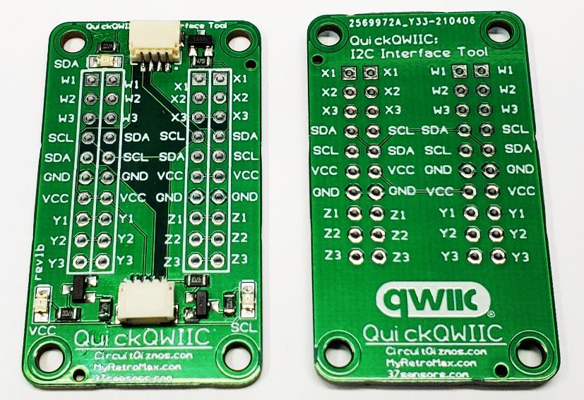 This is a prototype/interface board to make it easy to interface various I2C modules to use the QWIIC connectors on the RetroMax 2.3a. QuickQWIIC Interface Board There are a lot of QWIIC modules available with the QWIIC connector already on them from SparkFun, Adafruit (called STEMMA QT), and others. I2C device modules are often available in the "37 sensor" kits and also from Amazon, eBay, AliExpress, etc. 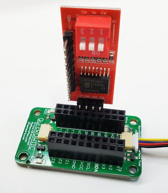 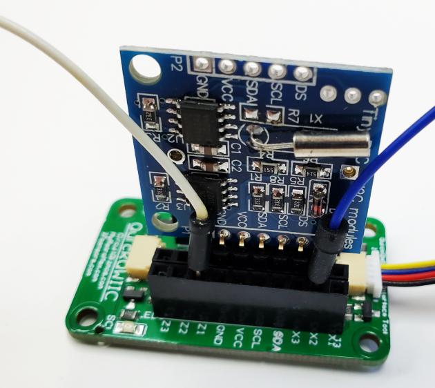 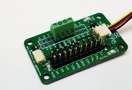 The CircuitGizmos QuickQWIIC interface board lets you interface various modules to the QWIIC bus. It is a great way to make any I2C module/board into a Qwiic-enabled board. The QWIIC interface can be found on various development boards. The QuickQWIIC has dual QWIIC headers on the board to facilitate a daisy-chain from the controlling QWIIC device to other QWIIC devices. Several boards can be chained together to put more than one I2C device on a bus. In the center of the QuickQWIIC are rows of plated-through holes with the four connections of QWIIC (power, ground, data, clock) arranged in different order to make connecting to I2C modules with their own arrangement of these signals easier. If you have an I2C module with a 4 pin header that has power, ground, data, and clock in that order it is easy to find those pins on the QuickQWIIC in that same order. If power and ground are swapped, there is a row on the QuickQWIIC that will support that. You can order a QuickQWIIC bare board or a board with the surface-mount parts populated. A third option includes a selection of .1" header sockets. The red board in the images is an I2C module attached to the QuickQWIIC in the appropriate place for the order of the power, ground, data, and clock signals. By being plugged into the QuickQWIIC board this PCF8574A Remote 8-Bit I/O Expander becomes a QWIIC bus peripheral. The blue board in the images is an RTC module (DS1307) with an EEPROM (24C32). The QuickQWIIC board makes this module a QWIIC bus peripheral. The BAT connection of the board lands in the Z1 position on the QuickQWIIC board. A jumper wire inserted into the other Z1 position can be used to connect to an external battery for this module. There are 12 pairs of these utility connections on the QuickQWIIC module. Edited 2021-07-02 13:16 by CircuitGizmos Micromites and Maximites! - Beginning Maximite |
||||
TassyJim Guru Joined: 07/08/2011 Location: AustraliaPosts: 6536 |
If your programs check MM.DEVICE$ for compatibility, you may need to make a small change to cater for the Second Gen. MM.DEVICE$ = "Colour Maximite 2" for Gen 1 and "Colour Maximite 2 G2" for the Gen 2 devices. The easiest way to cover both versions is to use IF INSTR(MM.DEVICE$,"Colour Maximite 2") THEN ' we have version G1 or G2 or IF INSTR(MM.DEVICE$,"G2") THEN ' we have version G2 I have updated my video mode test program to suit. https://www.c-com.com.au/mmhelp/testcard.htm The full colour modes look great in the test program but for most purposes, the existing faster modes will continue to be the best choice. Jim VK7JH MMedit |
||||
| bar1010 Senior Member Joined: 10/08/2020 Location: United StatesPosts: 197 |
Thanks for this new Generation 2 version of the Color Maximite 2. This will be great! Am hoping for around 2 megabytes RAM for MMBasic programs and perhaps double the firmware max size to allow for many additional modifications to MMBasic. Am wondering if a VGA to HDMI converter will be necessary for the new 1920x1080 mode. |
||||
| Geoffg Guru Joined: 06/06/2011 Location: AustraliaPosts: 3362 |
Program memory is 516KB with 24MB RAM for variables, buffers, etc (in the Generation 2 design). The ARM CortexM7 does not support HDMI, so an expensive and complicated controller chip would be required. There are also difficulties associated with HDMI licensing, so this feature was just not practical. Especially given that VGA to HDMI converters are readily available and inexpensive. Geoff Geoff Graham - http://geoffg.net |
||||
| siwypiotr Senior Member Joined: 18/08/2020 Location: PolandPosts: 127 |
Congratulations to Peter and Geoff for creating new Maximite model! 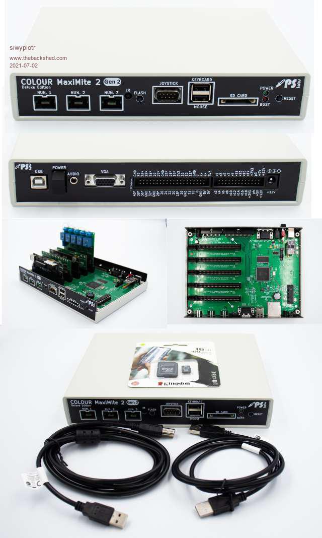 PS Labs is happy to announce release of new Color Maximite 2 Deluxe GEN2 model. This model is made with compliance with new GEN2 standard. One many new features are: - Double RAM (from 16 to 32 MB) - High resolution graphical mode - 24 bit color - 5 x Build in edge connector for expansion cards - 3 x Nunchuk port - 1 x Atari joystick port with over voltage protection - Build in RTC clock from - Build in HT mouse controller chip - Build in ESP01 WiFi module Can be purchased here: https://sklep.pslabs.pl/Colour-Maximite-2-GEN2-Deluxe-Edition-USB-Host-Contr-WiFi-p171 Manual and Github resources can be found here: https://github.com/pslabs-ps/CMM2-DeluxeEdition-GEN2 Expansion system Github resources can be found here: https://github.com/pslabs-ps/CMM2-Expansion-System 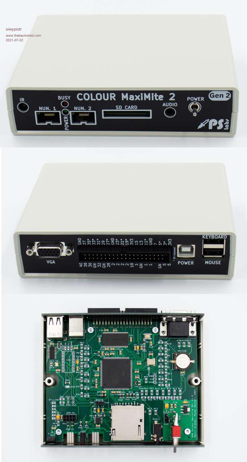 We are also offering GEN2 model with PCB identical Peter Mather design with build in RTC chip. Can be purchased here: https://sklep.pslabs.pl/Colour-Maximite-2-GEN2-p172 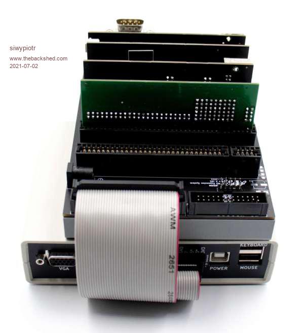 This model and all other models can be expanded with our expansion system: https://github.com/pslabs-ps/CMM2-Expansion-System |
||||
| TassyJim Guru Joined: 07/08/2011 Location: AustraliaPosts: 6536 |
My old monitor has no trouble with 1920 x 1080 and I expect that most widescreen monitors in use today will be the same. Jim VK7JH MMedit |
||||
| Volhout Guru Joined: 05/03/2018 Location: NetherlandsPosts: 5921 |
Geoff / Peter, Nice upgrade, the generation 2 ! Is the 3.5mm audio jack compatible with headsets (32ohm / 600ohm) ? Since it is in the front, you expect it to be. Volhout AFAIK the 2 main confusions with gen 1 where - keyboards - audio (DC bias and high impedance) PicomiteVGA PETSCII ROBOTS |
||||
| TassyJim Guru Joined: 07/08/2011 Location: AustraliaPosts: 6536 |
The audio has 4.7k resistors in series with the output so it is safe to connect low impedance speakers without the distortion. There aren't any DC blocking capacitors so the output is available for DC level outputs if desired. The main reason for problems with the Gen 1 audio was due to over-driving, not DC offset so the added resistors should be compatible with most systems. Jim VK7JH MMedit |
||||
| Volhout Guru Joined: 05/03/2018 Location: NetherlandsPosts: 5921 |
Hi Jim, After I posted I checked the schematics on Geoff's site. And noticed the same. To bad they did not fix this. When the audio was on the rear panel, you could argue that the 3.5mm jack was chosen since there was not enough space on the rear panel to accomodate the high impedance RCA (red/white) audio pair. But now audio is on the front panel, with a connector type that is common for headphones, it is an invitation to connect headphones. A missed opportunity.... Volhout Maybe for Gen 3 .. ? Edited 2021-07-02 18:29 by Volhout PicomiteVGA PETSCII ROBOTS |
||||
| thwill Guru Joined: 16/09/2019 Location: United KingdomPosts: 4369 |
Nice work folks. My vote is that Gen 3 should have a bank of LEDs and toggle switches ... it doesn't have to be functional, just retro. Best wishes, Tom MMBasic for Linux, Game*Mite, CMM2 Welcome Tape, Creaky old text adventures |
||||
| Mixtel90 Guru Joined: 05/10/2019 Location: United KingdomPosts: 8895 |
CMM2 Generation X - or maybe not. 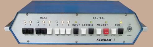 I've been working on a version of this, on a single 14-pin PIC. It's a project I started a couple of years ago but decided that I needed hardware to be able to go much further with the software (written in GCBASIC). It's still slowly ongoing - at least I'm making the pcbs. :) Of course, as it has buttons rather than toggle switches it might be far too advanced for you, Tom. ;) Edited 2021-07-02 21:43 by Mixtel90 Mick Zilog Inside! nascom.info for Nascom & Gemini Preliminary MMBasic docs & my PCB designs |
||||
| CircuitGizmos Guru Joined: 08/09/2011 Location: United StatesPosts: 1427 |
This is fixed on the RetroMax 2.3a design (Generation 2 compatible) as it can drive headphones directly. You can plug headphones into the jack. Edited 2021-07-03 00:24 by CircuitGizmos Micromites and Maximites! - Beginning Maximite |
||||
| bar1010 Senior Member Joined: 10/08/2020 Location: United StatesPosts: 197 |
What is the reasoning for leaving the maximum program size at 516KB when 32MB RAM is available for Generation 2? What is the reasoning for allocating only 7MB of the 32MB RAM for video? It seems to me that if more was allocated for video then we could have 16bit color for 1920x1080 resolution mode. |
||||
| Mixtel90 Guru Joined: 05/10/2019 Location: United KingdomPosts: 8895 |
Can I ask what decided the value of 4k7 for the audio output resistors? That's a pretty high impedance output and probably wouldn't drive any commonly available headphones, although it's fine for active speakers or an amplifier input. 390R would give a maximum current of 8.5mA into a short circuit, so the output would probably be protected. It might also allow the connection of headphones as the audio output would be higher. Ok, it would put DC through the phones, but it probably wouldn't exceed 3mA or so which would be ok for most. It wouldn't give much output, but at least it might be usable and could handle down to 8R headphones safely. Mick Zilog Inside! nascom.info for Nascom & Gemini Preliminary MMBasic docs & my PCB designs |
||||
| matherp Guru Joined: 11/12/2012 Location: United KingdomPosts: 11475 |
What is the reasons for asking questions that a simple reading of the datasheet for the chip would answer. If you don't like what has been created that's fine but please don't post questions that imply that decisions made have been without thought or assume that I have time to explain each and every one. Edited 2021-07-03 07:45 by matherp |
||||
| thwill Guru Joined: 16/09/2019 Location: United KingdomPosts: 4369 |
C'mon Peter, if you haven't got an electronics background then chip data sheets are rather heavy going. In answer to the original question I believe (and may be completely wrong) that the 500 KB program limit is because programs need to be able to fit in the ARM microcontroller's flash and not the additional 32 MB RAM. I can't answer with regards the video other than guessing from Peter's answer it is a limit of what the microcontroller can drive. Best wishes, Tom Edited 2021-07-03 08:38 by thwill MMBasic for Linux, Game*Mite, CMM2 Welcome Tape, Creaky old text adventures |
||||
| TassyJim Guru Joined: 07/08/2011 Location: AustraliaPosts: 6536 |
The original design was for line level output and that hasn't changed. 4.7k is the usual impedance for line level. I did do some tests to see what minimum resistance was needed to prevent distortion at the processor end but can't readily find the info. It's somewhere here on TBS. To date, the vast majority of users have used PC powered speakers and 4.7k gives a good match to their typical 100 ohm to 2k input impedance while keeping the line level specs satisfied. There is nothing to stop you bypassing the 4.7k with whatever value you desire but to drive low impedance speakers, a voltage follower or similar would be required. Jim VK7JH MMedit |
||||
bigmik Guru Joined: 20/06/2011 Location: AustraliaPosts: 2981 |
Hi Geoff, Peter, All, Great work again  Is the detection of hardware (G1 or G2) based purely on memory size? If so can changing the Ram chip for a 4 times larger one (with the appropriate extra address line `bodged' in) utilise all of the extra video modes and program size, albeit with out the extra NunChuk and mouse support? Kind Regards, Mick Mick's uMite Stuff can be found >>> HERE (Kindly hosted by Dontronics) <<< |
||||
| Page 1 of 4 |
|||||
| The Back Shed's forum code is written, and hosted, in Australia. | © JAQ Software 2026 |
