
|
|
Forum Index : Microcontroller and PC projects : Microcontroller fault finding techniques
| Author | Message | ||||
| rogerdw Guru Joined: 22/10/2019 Location: AustraliaPosts: 952 |
Morning all, I fix circuit boards for a living and generally do ok ... though working solo can be a handicap at times because there's no one else to bounce ideas off. One of my biggest issues can be when I get a board that appears to have a fault around the micro area ... and I need to work out what! Just wondering what techniques you guys use for successful faultfinding ... and bear in mind that the gear I fix does not come with any circuit diagrams ... the most I will ever get is info on what the board is hooked up to and what it is expected to do. Once I've checked out the dc supply and clock signals I am at a loss. I have worked on a lot where the RAM or SRAM chips have failed ... so that is an area I focus on ... and also a lot where the flash memory chip has failed as well. Experience has shown me that it is very rarely the micro ... though that is not usually an issue because most of them are ROMless micros (fortunately) ... so sometimes in desperation I'll replace that as well. It's after that, that I get stalled and have no tools to get any further. One big plus is that often I'll have a batch of boards, so can sometimes identify something by using comparative methods ... but being all smd components makes it impractical to be swapping parts around. Plus add to that the fact they have thick layers of conformal coating all over them. Do any of you have techniques or procedures you use to fault find under these conditions. Thank you for any ideas you may have. Cheers, Roger |
||||
| SimpleSafeName Guru Joined: 28/07/2019 Location: United StatesPosts: 351 |
The conformal coating makes things really tough to fix. But I imagine that you already have stripping it off worked out. So I would recommend picking up a used logic analyzer with a pattern generator to write to each memory location and then read them back. Have the pattern generator "overwhelm" the address and data busses to do this. Put the CPU in perpetual reset or pull off the CPU to do this. With the CPU in reset you should be able to drive the busses safely. I've seen board hackers get ROM dumps in this fashion. Do you have pics that you can share? |
||||
| Volhout Guru Joined: 05/03/2018 Location: NetherlandsPosts: 5822 |
I generally recognize faults in 2 groups. 1/ digital chips failing internally (like a DRAM with defective memory cell). To find these faults you either need in-depth knowledge of the software, or have debug environment (different per chip). Alternative is blind replace chips. 2/ interconnects between chips (board faults and chip pin faults). Mostly these faults can be detected with a logic probe, multimeter or a impedance analyzer like this: Backpack Tracer PicomiteVGA PETSCII ROBOTS |
||||
| rogerdw Guru Joined: 22/10/2019 Location: AustraliaPosts: 952 |
I keep my meter probes really sharp so I can pierce the coating while fault finding ... and use solvent when I need to remove bits. Okay, that sounds interesting. I'll need to learn some new skills by the sound of it. I do recall while studying microprocessors about 40 years ago, that they suggested using a No-op code in the rom to make it cycle through all the addresses etc ... but never been able to find out anything about that or exactly the technique needed. Would have been a lot easier then with plug in devices, compared to the lovely smd's we have now!!! This is the type I've been struggling with this week, though I did get another two going today ... so a bit of progress. 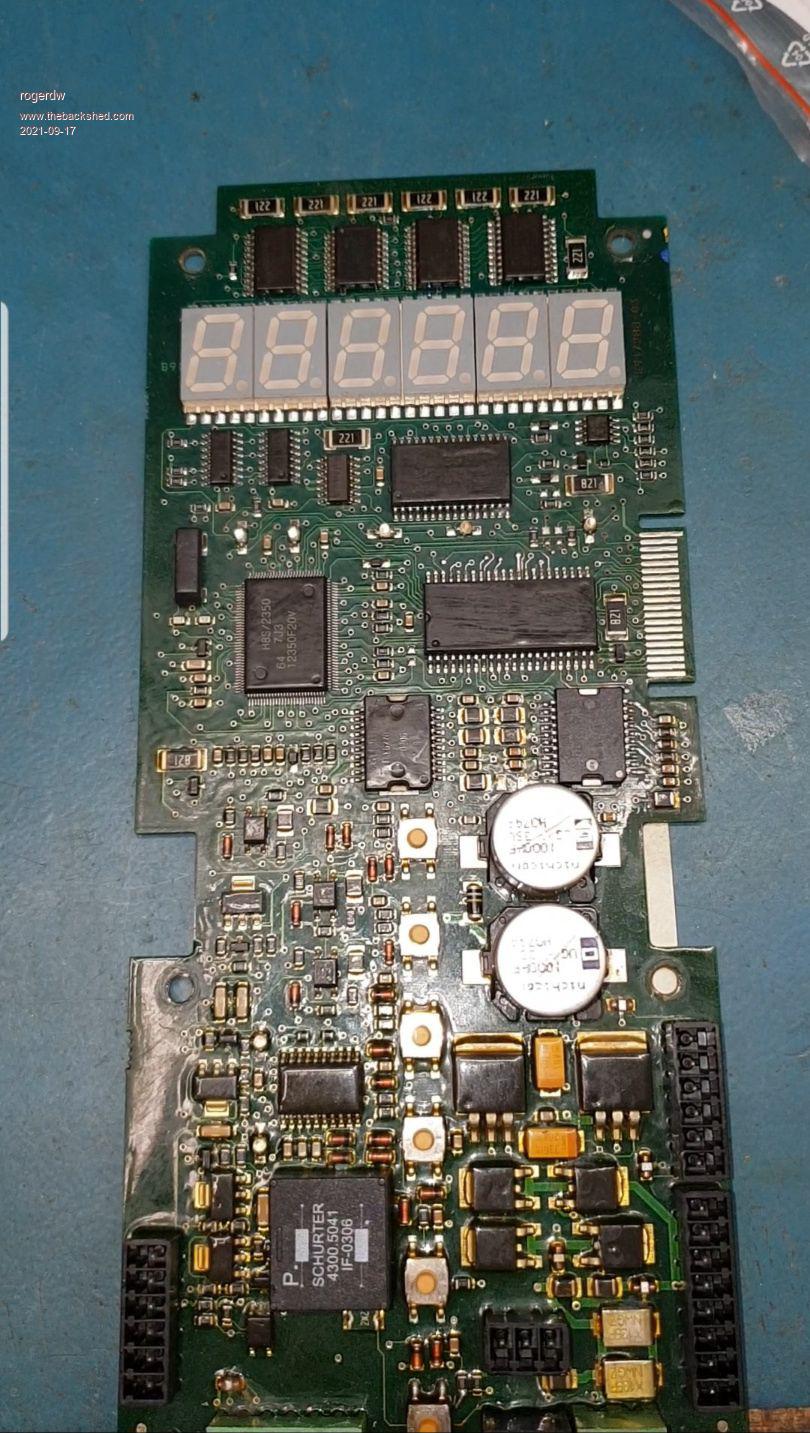 This is where the fault was with the first one ... two open circuit tracks right where they join to the feedthroughs ... underneath an SRAM chip. So much for the conformal coating ... seems some water got in under the chip and caused the issue. I had drawn out a reasonable amount of the circuit over the last 10 years or so ... but added a fair bit more to it over the last few days, which will certainly help in the future. Finding this fault gave me some hope for the next one ... but that ended up having a crook multiplexer IC ... 145 ohms between vcc and gnd. Took a while to find that too. 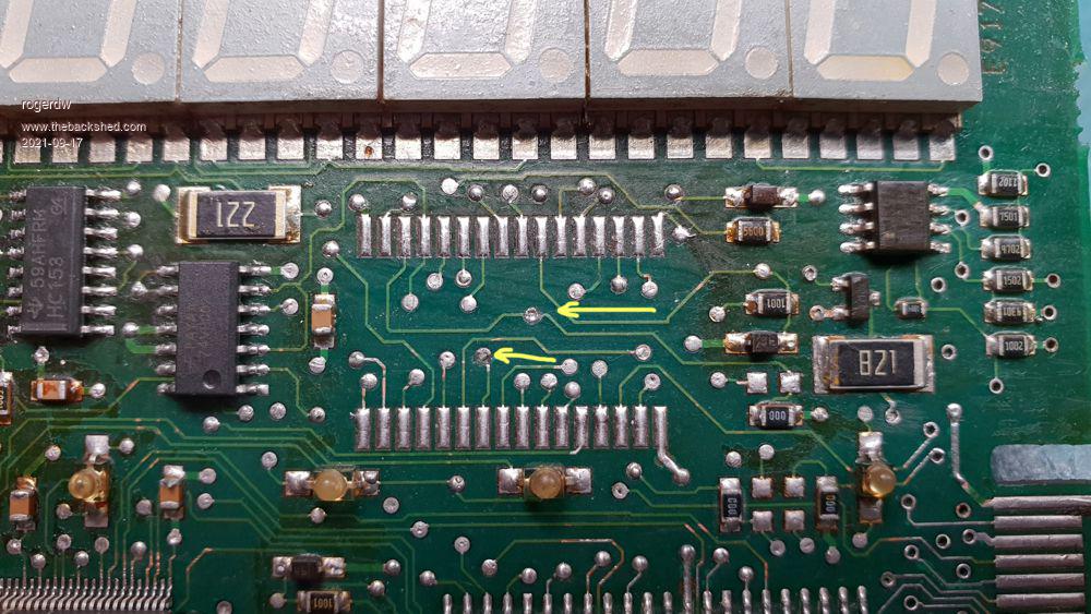 I'd had the micro off too in desperation ... but as usual that was unneccessary. And of course, always potential to create extra problems in the process. 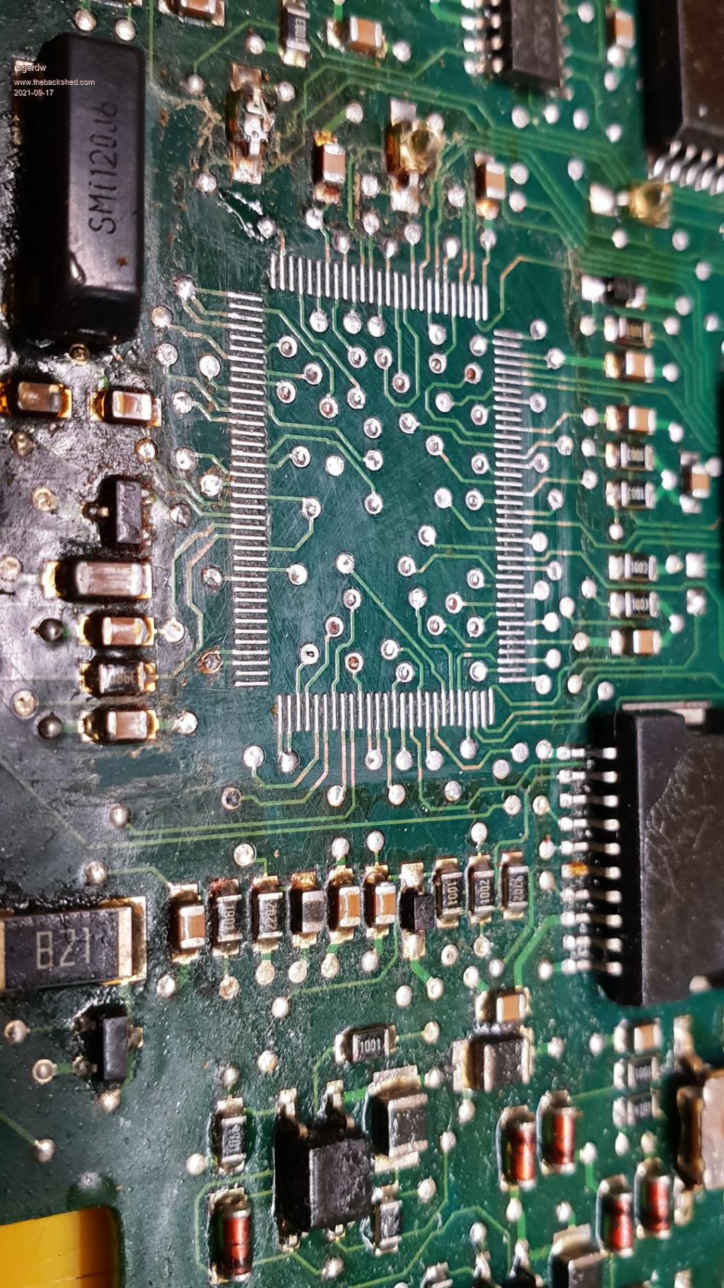 Cheers, Roger |
||||
| Mixtel90 Guru Joined: 05/10/2019 Location: United KingdomPosts: 8710 |
Eh... Back when I were a lad we used to get a spare Z80 (usually one of the slow ones that had gone cheap), bend out all the data pins and link them all together to 0v. That's a NOP on the Z80. Swap it into the device under test and watch the address bus count up with a logic probe (or, if you were rich, a scope). Use a slow clock and you could even use an audio probe - the Z80 has no minimum clock speed even if dynamic RAM has. 'Orrible things, these SMDs. Mick Zilog Inside! nascom.info for Nascom & Gemini Preliminary MMBasic docs & my PCB designs |
||||
| rogerdw Guru Joined: 22/10/2019 Location: AustraliaPosts: 952 |
Mmmm ... just blindly replacing chips when I'm desperate. I'd like to say using an educated guess, but when I hit a dead end I have to do something.  I've really only used a multimeter for years, though I do have a couple logic probes ... perhaps I'll drag them out and try them for various faults ... maybe they'll help. If I have any low resistance lines on the board I use a Polar instrument for detecting low resistance and that is brilliant for detecting shorted chips on the rail ... but like today, so often they are not shorted ... one had 145 ohms across it and of course the Polar can't pick that up. I've never seen the impedance analyzer you linked to, that may be a real help. I had a good read of that thread and will go back again to study it. Thanks to you both for your suggestions. Cheers, Roger |
||||
| rogerdw Guru Joined: 22/10/2019 Location: AustraliaPosts: 952 |
Okay, that makes more sense, thank you. I was thinking I had to somehow program the rom with a particular sequence ... though that would definitely be easier than trying to lift the data pins on the micro and link them all. Even without the conformal coat it would be difficult with the pitch size of these things ... but the coating makes such a mess of everything. Cheers, Roger |
||||
| Warpspeed Guru Joined: 09/08/2007 Location: AustraliaPosts: 4406 |
Roger, I did similar work for a company that specialized in fixing things where there was zero documentation. There are a whole range of techniques you can apply to repair boards without even powering them up, or even if you have no clue what its supposed to even do. None of this has much to do with traditional fault finding. The most obvious is a very careful visual check with a high powered stereo microscope. Dry joints, broken tracks, damaged components and such, can often be seen. Next step is to replace components known to have long term reliability or degradation problems such as small electrolytics, opto isolators, and discrete transistors. If you have a functioning board, and a non functioning board supplied by the customer to compare, signature analysis can tell you a lot by comparing the dynamic impedance of every node simultaneously on both boards with both boards powered down. This is especially good with analog circuits and finding electrostatic damage on digital boards. Slight electrostatic damage can be pretty insidious, where say a digital logic chip works, but only just. Electostatic damage on data or address busses can cause all kinds of problems that only occur occasionally. But the difference in dynamic impedance at a particular node between the known good board, and faulty board will often lead you directly to the faulty component. PROMS of various types are often just voltages stored on tiny internal capacitors that are supposed to stay "programmed" for maybe ten years. Once the charge leaks away, it starts to occasionally drop bits, and that is death to your firmware. If the date stamp is really old, and your program is corrupted, and the company that made the product is either out of business or non cooperative, your board can only go into the wheelie bin. Its not always possible to fix everything, but there are some unusual and not widely known about techniques that can very quickly result in success. Analog signature analysis is driving a node on a circuit board (with respect to common ground) with a suitable current limited ac voltage. By viewing the +/- voltage, on the x axis, and the +/- current on the y axis of a digital oscilloscope in XY mode, you will see a trace that can tell you rather a lot about the impedance at that node. Inductive or capacitive impedances open out and create a circle or ellipse through phase shift. Dc impedance creates just a line. For instance a diode will create a "L" shape because its a short in one direction and open circuit in the other direction. Zener diodes have their own characteristic shape too. Basically you put your probe on a node, say the base of a transistor, and you see a "shape" created on the oscilloscope screen. Then you shift your probe the exact same node on the other board and compare what you see. If its identical, you know the base and all the components around the base of that transistor are probably o/k. You don't need to even think about what you are seeing, if the traces look the same, move on to the next node. It takes about 30 seconds to go around a 40 pin chip testing and comparing every pin alternately on each board. Any radical difference on a certain pin between the good board and faulty board can be investigated further. It could be the chip, or something external connected to that particular pin. It might take an hour or more to go through every possible node on a complex board, but if you have no circuit, or know what the board is even supposed to do, its time well spent. Sometimes you might be presented with a small plug in board to fix that plugs into a card cage of a much larger system. Maybe a ram board, or obscure interface board for example, and there is simply no possible way to power it up and test it without the rest of the system or any service information. Its just too easy to blow things up. Sometimes this works, and sometimes not. But it can produce some really worthwhile successes in a fairly short time that would not otherwise be possible. Google analog signature analysis for more info. Edited 2021-09-17 14:34 by Warpspeed Cheers, �Tony. |
||||
| Mixtel90 Guru Joined: 05/10/2019 Location: United KingdomPosts: 8710 |
There is a useful tool that I can't remember the name of! It measures track continuity using a voltage of about 0.2-0.3V IIRC. The idea is that you can work on a "dry" board and all semiconductors and resistors of any significant value are ignored. There's probably a commercial version, but I'm sure I saw a circuit for one. Uses the differential properties of an op-amp IIRC. As you can see from my sig, I have an interest in the old Nascom and Gemini systems. From the Nascom 2 onward we do come across "PROM rot", losing data (and sometimes the actual pins on the package! This stuff is 40+ years old and hasn't always been used or stored in ideal conditions). We also lose data from old EPROMs (especially 2708). Mick Zilog Inside! nascom.info for Nascom & Gemini Preliminary MMBasic docs & my PCB designs |
||||
| CaptainBoing Guru Joined: 07/09/2016 Location: United KingdomPosts: 2171 |
not a technique, but consider using a pcb test jig that holds the board securely and has "cranes" with wired pogo-pins that can easily be positioned to contact specific parts of the board. Its then really easy to get onto interesting bits of the PCB without slipping or dislodging other bits. I don't use it often but when i have a right sod of a problem, this is a godsend. Not having to "be careful" but having 8 umbilicals that reach all points of concern removes the risk of knocking things out and shorting pins with probes - which makes the debug go smoother. I 3D printed mine and it works really well. The original design used acupuncture needles as probes. I have a mixture of cranes with those and pogo-pins (which do for most things) but for tiny SMD package ICs, the needles can be very helpful. I saw this later which made me think about options for testing ram chips (old stylee) https://www.youtube.com/watch?v=_99HNsxgLRw One of several low-cost chip testers. I suspect you'd be making up some adaptors for it. Edited 2021-09-17 22:46 by CaptainBoing |
||||
| rogerdw Guru Joined: 22/10/2019 Location: AustraliaPosts: 952 |
Yeah, I have to learn to slow down sometimes. It's embarrassing when I spot a visual clue after half an hour of working on a board ... when I could have easily picked it up if I'd had a thorough look. There are certainly boards I know well where I do exactly that ... replace a handful of parts that I know cause a lot of issues. That is something I do often have ... and it can make a real difference having another to compare with. I got a box of nine boards in today, all the same type ... as well as a couple one-offs. Week before last I got a huge box with about 50 sets of boards. That alone's gunna take me a month or more to do. Sometimes in desperation I've compared boards side by side for resistance to ground or rail ... and it's amazing how often that has provided clues for further investigation ... but it is pretty crude and not as successful as it could be. That's where having a known good board can be helpful. I've managed to score firmware off a lot of boards by removing the memory chips and saving a copy ... then when I suspect a crook one ... I program a new chip and stick it in. Often that solves my problem. The boards I've shown can have their firmware updated in the field ... and I do have the processor and files for them ... the problem is that it requires the board to have a good working flash chip because it uses the boot program section to do the job. So I load a new chip with a file I've copied ... and once stitched on the board I can update it to the required version. Again, on the boards shown, I've spent ages trying to work out how I can simply solder on a new flash chip ... then program it fully from the sockets on the edge of the board ... but I'm not clever enough for that (so far). That sounds really useful. So is that the same as what Volhout was describing and linked to above? Looks like it's something I need. Yes, definitely has the potential to solve a lot of my tricky boards. I need that system. Yes, it is a fairly common occurrence ... and I am amazed that I often can fix stuff like that ... but it's usually more good luck than good management. Thanks for the explanations. Cheers, Roger |
||||
| rogerdw Guru Joined: 22/10/2019 Location: AustraliaPosts: 952 |
Thanks for those suggestions. I'll look more into that as well. Now that you've mentioned "Prom rot" ... I've certainly seen symptons like that plenty of times. Nowadays I program and fit a new chip if I have the correct file ... but it explains why sometimes I can reboot a board ... maybe four or five times ... and then finally it reboots properly and then runs ok. If what you described is happening ... is it likely to be okay again for a while ... or is it likely to fail again fairly quickly. I haven't had lots of issues with recalls or anything ... but I may just have been lucky to get away with it. I may be able to do that with some boards ... but most with the conformal coating probably would not work. I have to regularly sharpen my probes to punch through ... and very often I have to go back over because it's so hard to get reliable readings. I'll certainly give it some thought though because it could save me a lot of time if I could make it work. Yes, it's the slippimg that worries me the most ... having to put so much pressure on the probe to cut through the coating often leads to slipping ... and on a powered board, that's not good!!! I enjoyed the video on the chip tester ... didn't know about them ... though most of mine are smds, so a bit hard to transfer the tech to accommodate them. Thanks for your input guys, I'm learning a lot. Cheers, Roger |
||||
| CaptainBoing Guru Joined: 07/09/2016 Location: United KingdomPosts: 2171 |
not my work, but this is the one I printed - works well. Is a dream when I have to get the saleae out (bugs fall fast when that is on the job!) source is here https://www.thingiverse.com/thing:3615910 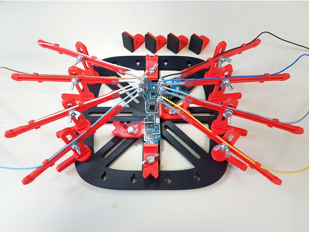 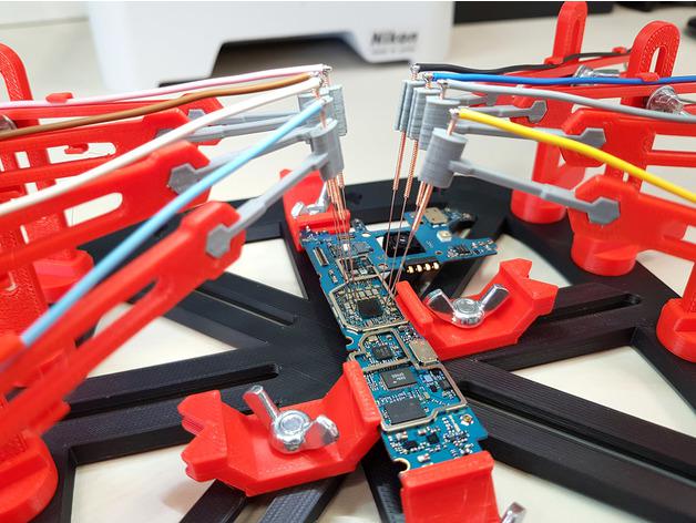 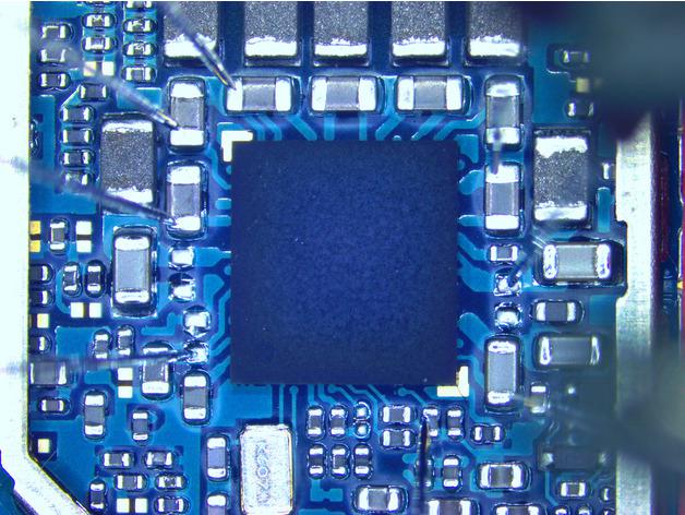 Edited 2021-09-18 02:46 by CaptainBoing |
||||
| Mixtel90 Guru Joined: 05/10/2019 Location: United KingdomPosts: 8710 |
A thing of beauty indeed! Almost worth shelling out for a 3D printer! (If I had anywhere to put one) Mick Zilog Inside! nascom.info for Nascom & Gemini Preliminary MMBasic docs & my PCB designs |
||||
| Warpspeed Guru Joined: 09/08/2007 Location: AustraliaPosts: 4406 |
Yes, its definitely a similar version of the exact same concept. You mentioned measuring resistance to ground, this does exactly that, but the information on how the ac impedance to ground changes with voltage, and any reactive component present will be FAR more revealing than simply a dc reading on an ohm meter. Many nodes have PN silicon junctions involved, and the impedance changes quite dramatically with voltage, something an ohm meter just cannot see. To be useful the range of current applied and voltage measured, plus the frequency of the applied test signal will have a large effect on what you can actually see on your display. We might be looking at some very high or very low impedances for example. As with a resistance check, a suitable measurement range needs to be selected to get useful information. Also, the expected values of inductance and capacitance can vary hugely in different types of circuit, so the applied ac test frequency may need to be selected appropriately. There may be picofarads or microfarads involved at a particular node which may appear as just an open circuit or a short circuit. But with a suitable test frequency selected, a nice open loop will give a pretty good indication of slight differences in capacitance between the two corresponding nodes under test. Its just like driving an oscilloscope, you need to set the ranges appropriately to see any small detail. Some commercial instruments have two completely separate measurement channels with two probes so you can probe the same node on two different boards simultaneously, and see two traces in different colours overlayed on the screen. That is nice, but not strictly necessary. Being able to see maybe a very few percent difference will only be indicating component tolerances. If there is a hard fault, the difference will be very dramatic and difficult to overlook. Cheers, �Tony. |
||||
| CaptainBoing Guru Joined: 07/09/2016 Location: United KingdomPosts: 2171 |
wouldn't be without mine now - I can make parts for any applicable situation. Liberating is what it is. from tiny complex enclosures/connectors to the just-finished set of jobs that took 43 hours total - the giant hinges for the corners of the "winter quarters" for our chickens. Edited 2021-09-18 16:41 by CaptainBoing |
||||
| Tinine Guru Joined: 30/03/2016 Location: United KingdomPosts: 1646 |
In this scenario, I ask myself if I can simply recreate the functionality. The amazing Mites can do a lot |
||||
| The Back Shed's forum code is written, and hosted, in Australia. | © JAQ Software 2026 |
