
|
|
Forum Index : Microcontroller and PC projects : CMM2 Gen 1 rear I/O connector to PS2 mouse adapter
| Author | Message | ||||
| Matty_Vee Newbie Joined: 06/10/2020 Location: AustraliaPosts: 2 |
Hi all, Anyone knocked up a mouse adapter for the gen 1 CMM2? I assume the neatest way would be via a raspberry pi breakout board? Just looking for some ideas as I'm pretty new to this. Cheers, Matt |
||||
| Mixtel90 Guru Joined: 05/10/2019 Location: United KingdomPosts: 8683 |
I did an internal mod that I found on here, bringing a USB socket out to the RHS. Using right-angle USB converter has brought the mouse lead out at the back, and the GPIO port clear. A later mod to the mod that I have in mind is to have a jumper on the RHS that will disable the pullup resistors for the mouse and leave the GPIO port clean. Mick Zilog Inside! nascom.info for Nascom & Gemini Preliminary MMBasic docs & my PCB designs |
||||
| Matty_Vee Newbie Joined: 06/10/2020 Location: AustraliaPosts: 2 |
Ok, that sounds neat. Trying to find it on the forums now. I assume that uses a mouse using the USB plug but in a PS2 compatible mode? |
||||
| Mixtel90 Guru Joined: 05/10/2019 Location: United KingdomPosts: 8683 |
This is the mod: https://www.thebackshed.com/forum/ViewTopic.php?TID=13305&PID=162296#162296#162296 I put the pull-ups from pins 32 (data) & 33 (clock) inside, under the PCB. My intention is to feed the supply side of them via diodes from the centre of a 2-way link, either to supply (mouse on) or to ground (mouse isolated). My mouse is a cheap white one that lights up brilliantly in red and blue. I don't lose it easily. It is a USB in PS2 compatible mode, yes. Mick Zilog Inside! nascom.info for Nascom & Gemini Preliminary MMBasic docs & my PCB designs |
||||
| paceman Guru Joined: 07/10/2011 Location: AustraliaPosts: 1329 |
Yes Matt, checkout Mick's link. That's my post and it's still working fine. The tricky bit is breaking into the mouse lead for the pullups but that approach does leave the CMM2 bog standard which is handy. If you don't think you're ever going to use pins 31 and 33 for anything else then putting the pullups inside prior to the USB connectors will save you some time doing the mod. Greg |
||||
| Mixtel90 Guru Joined: 05/10/2019 Location: United KingdomPosts: 8683 |
If I can just put my hands on that long-handled link (that I'm sure I have "somewhere safe") I'll do that additional isolation mod on mine. I did consider just putting a link on the bottom, but it would need a reasonable size hole to get to it to make the changeover. I didn't want to put the resistors in the mouse lead as I may want to change the mouse at some point. Just a couple of points for those who intend doing this mod: The top side copper is at 3v3 and the bottom side is GND. It's *very* important that you remove the top side copper from around the socket lugs before you solder it in. A few twists of a drill does it nicely. The socket has plastic mouldings on the bottom so it doesn't rest on the top copper. The FR4 PCB material is *very* hard and cutting the slot may be difficult using ordinary drills (use a sharp one). I just happened to have a solid tungsten carbide bit that did it nicely. Finished off with a little diamond file. The adapter that I used is described as a RIGHT direction. The ebay ad was confusing as the photo was of a LEFT version. :) It's a very neat mod, Greg. :) Your pics were excellent. Thanks! Mick Zilog Inside! nascom.info for Nascom & Gemini Preliminary MMBasic docs & my PCB designs |
||||
| paceman Guru Joined: 07/10/2011 Location: AustraliaPosts: 1329 |
Thanks Mick, I think I enjoy the drilling/soldering stuff more than the software, it must be the metallurgist in me. I did stuff up a bit in my post above though - it's pins 32 and 33 of course, not the 31 and 33 I said. Greg |
||||
mclout999 Guru Joined: 05/07/2020 Location: United StatesPosts: 502 |
Why not make a cable as I did for my Gen 1. It allows you to use either PS/2 connectors or USB for those duel mode mice. The two pull-up resistors are inline. It is very robust and works well. I am adding a ESP-01 WIFI module when it arrives so I have WIFI and mouse on one cable for my Gen 1. It won't look elegant but it should work well. 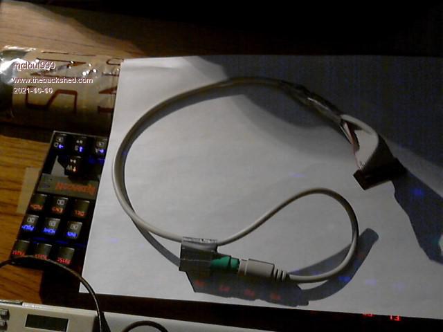 They call me Shai-Hulud (The maker) |
||||
| Mixtel90 Guru Joined: 05/10/2019 Location: United KingdomPosts: 8683 |
Just doing the rest of my mod at the moment. We'll see how it works out. :) Mick Zilog Inside! nascom.info for Nascom & Gemini Preliminary MMBasic docs & my PCB designs |
||||
| Mixtel90 Guru Joined: 05/10/2019 Location: United KingdomPosts: 8683 |
Yippee!! It's working! :) 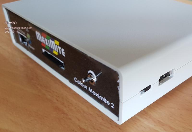 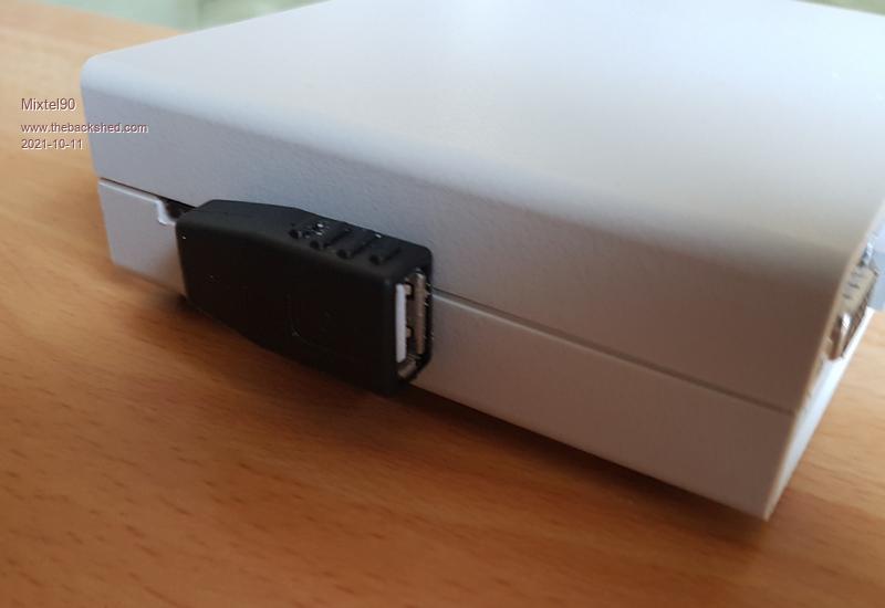 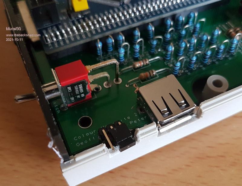 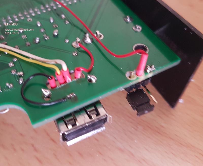 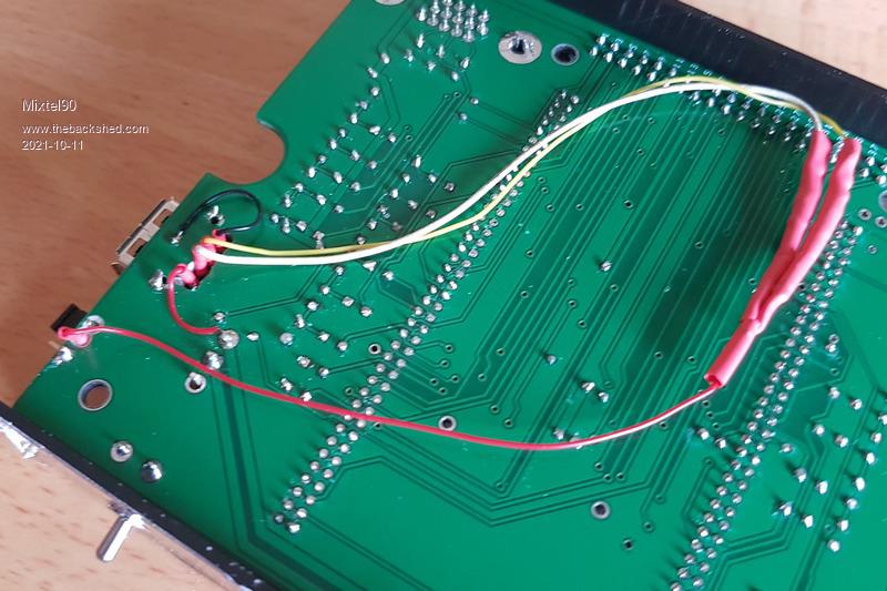 The link switches the common anodes of the diodes between 3V3 (mouse enabled) and ground (mouse disabled - the diodes are reverse biased so the resistors are effectively out of circuit). Each diode cathode feeds a pull up resistor, one to pin 32 and one to pin 33. Mick Zilog Inside! nascom.info for Nascom & Gemini Preliminary MMBasic docs & my PCB designs |
||||
| The Back Shed's forum code is written, and hosted, in Australia. | © JAQ Software 2026 |
