
|
|
Forum Index : Microcontroller and PC projects : picoMite with Waveshare pico LCD 1.3
| Author | Message | ||||
| lali Newbie Joined: 07/01/2022 Location: United StatesPosts: 4 |
Greetings, Newbie here. I have successfully configured an SD card and a DHT11. Programmed a dump to linux screen using VT100 escape sequences to format. Boring. I wanted an LCD screen. I bought a Waveshare pico-LCD-1.3 and a bus expander thinking it would reduce the spaghetti. I can not figure out how to configure OPTION SYSTEM SPI for the SD card and the LCD to work The LCD Reset pin conflicts with MISO on the pico. The LCD has headers that allow direct connection to the rpi pico, so obviously I needed the bus expander. I think I'm going to have to wire from the LCD header to a breadboard to avoid the conflict. Has anyone else seen this? Thanks for your help, Larry |
||||
| matherp Guru Joined: 11/12/2012 Location: United KingdomPosts: 11100 |
How are you connecting the SDcard? Flying leads or does it plug to the Pico directly? If the latter post a link so we can see if there is a resolution If the former then I've just tested it successfully 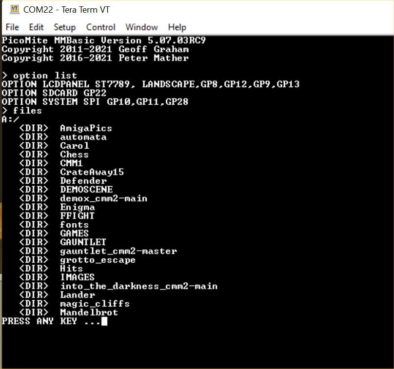  Edited 2022-01-08 04:55 by matherp |
||||
| lali Newbie Joined: 07/01/2022 Location: United StatesPosts: 4 |
Hi Peter, I'm using flying leads to the SD card. I really don't understand your use of GP28 in the option system spi statement. That looks like ADC2 and not an spi pin. What am I missing? I'll try it just as you've shown and report back. Larry |
||||
| andreas Senior Member Joined: 07/12/2020 Location: GermanyPosts: 226 |
Hello Larry, this is my setup. I have an LCD-screen, DHT sensor, RealTime clock and SDCard reader using a single power supply 5V. The 3.3V are generated by and voltage regulator on the breadboard. I have connected power to the VSYS pin of the pico. The RTC and the sensor are using 3.3V. The SDCard has it's own voltage regulator to generate 3.3V. When I want to programm that setup I use PuTTy under Linux and connect an USB cable on the fly. PuTTy shows nice colours when programming within an Edit-session. > option list OPTION CPUSPEED (KHz) 133000 OPTION DISPLAY 50, 100 OPTION LCDPANEL ILI9341, LANDSCAPE,GP15,GP14,GP13 OPTION GUI CONTROLS 75 OPTION TOUCH GP12,GP11 OPTION AUTORUN ON OPTION COLOURCODE ON OPTION SDCARD GP5, GP2, GP3, GP4 OPTION SYSTEM SPI GP18,GP19,GP16 OPTION SYSTEM I2C GP20,GP21 OPTION RTC AUTO ENABLED  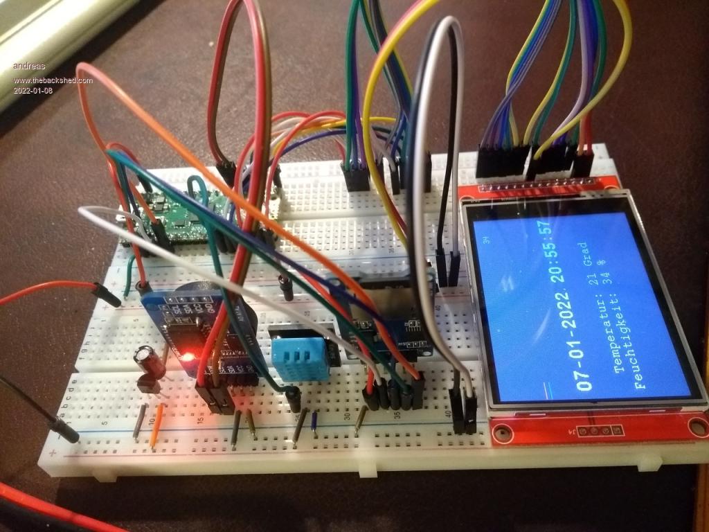 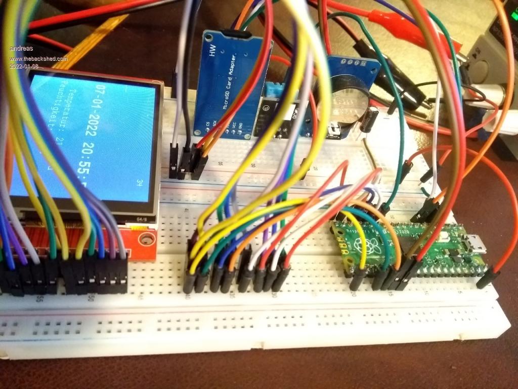 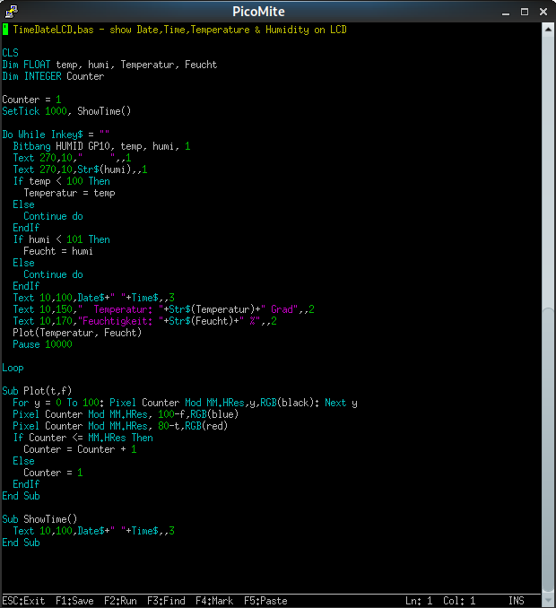 |
||||
| lali Newbie Joined: 07/01/2022 Location: United StatesPosts: 4 |
Andreas, Thanks for your reply. I've solved the LCD issue with help from Peter. Your pictures were very useful and highlighted another problem. I have several of the same SD card adapter that you show. All of mine always fail with error messages which I neglected to write down. I replaced that adapter with one from Adafruit and it works fine. Have you had any issues with your adapter? Larry |
||||
| andreas Senior Member Joined: 07/12/2020 Location: GermanyPosts: 226 |
Hallo Larry, yes there were problems as long as I tried to use the USB cable from the PC as the single power source. I could read but nut write. Writing "unmounted" the SDCard. When I started using an external power supply reading and writing was fine. I think the SDCard needs more power for writing and therefore a good power source. The advantage of connecting the 5V to VSYS and not to VBUS is, that my external power supply will not source power into the PC because there is a diode between VBUS and VSYS. The pico takes the power which is higher either VBUS from the PC or VSYS from the external source. This way I can connect the USB cable at any time. The pico will continue to run as log as there is external power supply connected. -andreas |
||||
| lali Newbie Joined: 07/01/2022 Location: United StatesPosts: 4 |
Andreas, Time to dig out the bench supply. I've been relying on USB so long, I'm not sure where it is! Larry |
||||
| andreas Senior Member Joined: 07/12/2020 Location: GermanyPosts: 226 |
 |
||||
| Mixtel90 Guru Joined: 05/10/2019 Location: United KingdomPosts: 8683 |
There is very rarely a problem with powering PicoMite stuff from USB. The Pico module is happy at down to less than 2V input on VSYS as the buck-boost SMPS will handle it. If you happen to be using a laptop with a particularly weak USB supply output it's well worth getting a powered USB hub anyway. SDcard power often needs filtering because of surges. Try a series resistor of 2R2 from the 3V3 supply and a 50-100uF capacitor, bypassed by 0.1uF, to ground. Some adapters (particularly some labelled "for Arduino") have series resistors on the signal lines which can cause problems with some cards. It's usually worth avoiding those. Mick Zilog Inside! nascom.info for Nascom & Gemini Preliminary MMBasic docs & my PCB designs |
||||
| andreas Senior Member Joined: 07/12/2020 Location: GermanyPosts: 226 |
Hello Mick, I will do that today, have time over the weekend to play a little. Would be very nice to have USB as the only power supply. Power specs should be ok using USB: USB 2.0 5 Volt 0,5 A 2,5 W USB 3.0/3.1/3.2 5 Volt 0,9 A 4,5 W -andreas Edited 2022-01-08 19:45 by andreas |
||||
| JohnS Guru Joined: 18/11/2011 Location: United KingdomPosts: 4281 |
Has the (pico) device asked for so much? If not, it will get less and then surges may matter more. John |
||||
| Mixtel90 Guru Joined: 05/10/2019 Location: United KingdomPosts: 8683 |
Peter always includes filtering for the SDcard now and it seems to work. :) I've used SDcards without filtering successfully but not every time. If you reduce the CPU speed on the PicoMite the supply current drops so that could be used to take some load off the USB (but it's not a big difference). I think you can go down as low as OPTION CPUSPEED = 48000 Demand on the USB doesn't get anywhere close to 500mA unless you have a lot of add-ons. Mick Zilog Inside! nascom.info for Nascom & Gemini Preliminary MMBasic docs & my PCB designs |
||||
| andreas Senior Member Joined: 07/12/2020 Location: GermanyPosts: 226 |
Hello Mike, the low pass filter did solve my SDCard-writing-problem. Many thanks for that hint! I use two of them. One for 5.0V and one for 3.3V. I took a different value for the capacitor because I had no 50uF or 100uF here. But seems to be that 10uF will do. 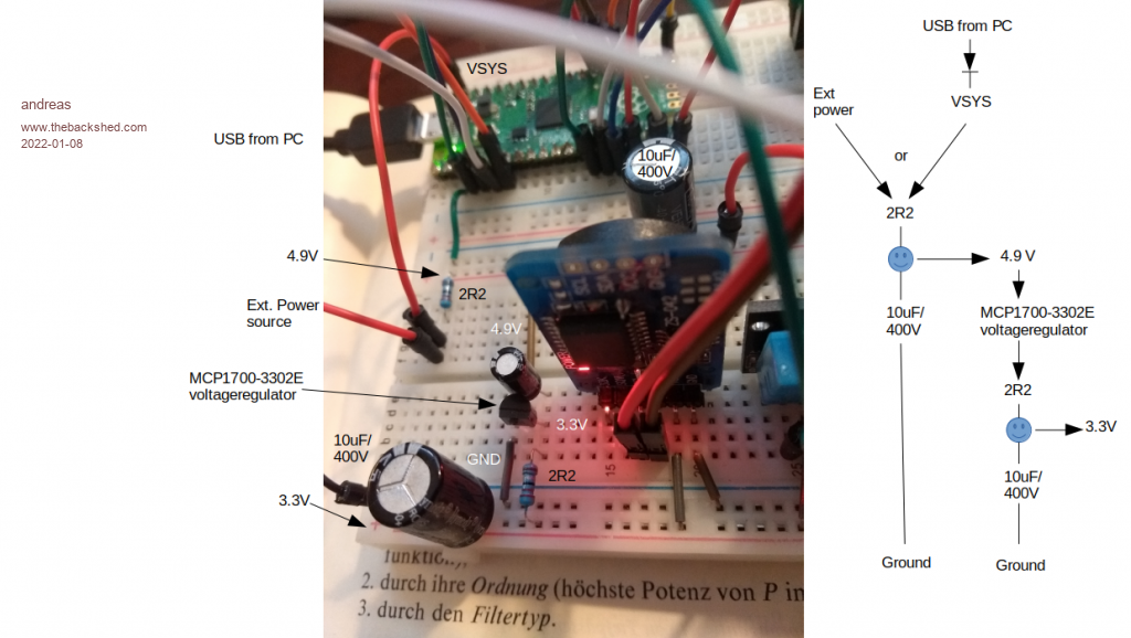 -andreas |
||||
| The Back Shed's forum code is written, and hosted, in Australia. | © JAQ Software 2026 |
