
|
|
Forum Index : Microcontroller and PC projects : PICOMITE oscilloscope
| Page 1 of 3 |
|||||
| Author | Message | ||||
| ztoti Regular Member Joined: 27/10/2011 Location: CanadaPosts: 65 |
Hi there, This is a question for Peter: I used your Cfunction Scope for PIC 32MX470 and I can say it works great, I'm so happy with it. Now with all this corona situation: 1. I can't find PIC32MX470 in DigiKey 2 RPi PICO is 1/2 of the price of PIC32MX470 I know you are so busy with MMBasic for Windows, Linux, Picomite... but is there any chance to "translate" this beautiful Cfuncion for Picomite? Attached are the pictures from my GUI for the scope and gain (div/v) amplifier. Thank you 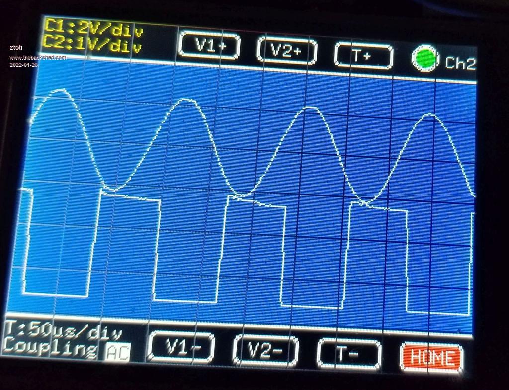 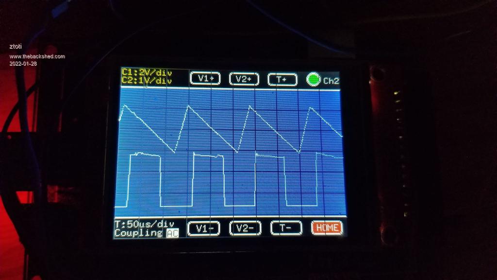 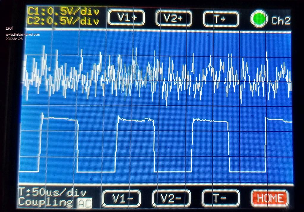 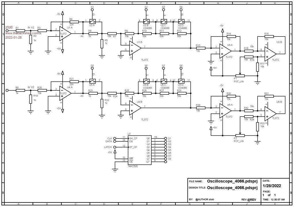 |
||||
| matherp Guru Joined: 11/12/2012 Location: United KingdomPosts: 11098 |
ADC command? |
||||
| ztoti Regular Member Joined: 27/10/2011 Location: CanadaPosts: 65 |
ADC command is OK but to slow. I tested CSUB, it works to f>150kHz. |
||||
| matherp Guru Joined: 11/12/2012 Location: United KingdomPosts: 11098 |
Check the ADC command up to 500KHz on one channel |
||||
| ztoti Regular Member Joined: 27/10/2011 Location: CanadaPosts: 65 |
OK, I'll try with it. Thank you. |
||||
lew247 Guru Joined: 23/12/2015 Location: United KingdomPosts: 1709 |
I've actually been thinking about this as well a cheap dual channel oscilloscope would be brilliant if it could be made to work with higher voltages which should be easy with a voltage divider circuit but there must be a better way The pico can run at 300Mhz and still use it's flash memory, and up to 420Mhz but unable to talk to the onboard flash at that speed so it could be pretty good as an oscilloscope This is as far as I've got circuit wise so far Anyone got any ideas for a better circuit to allow measuremeant of higher voltage lines? 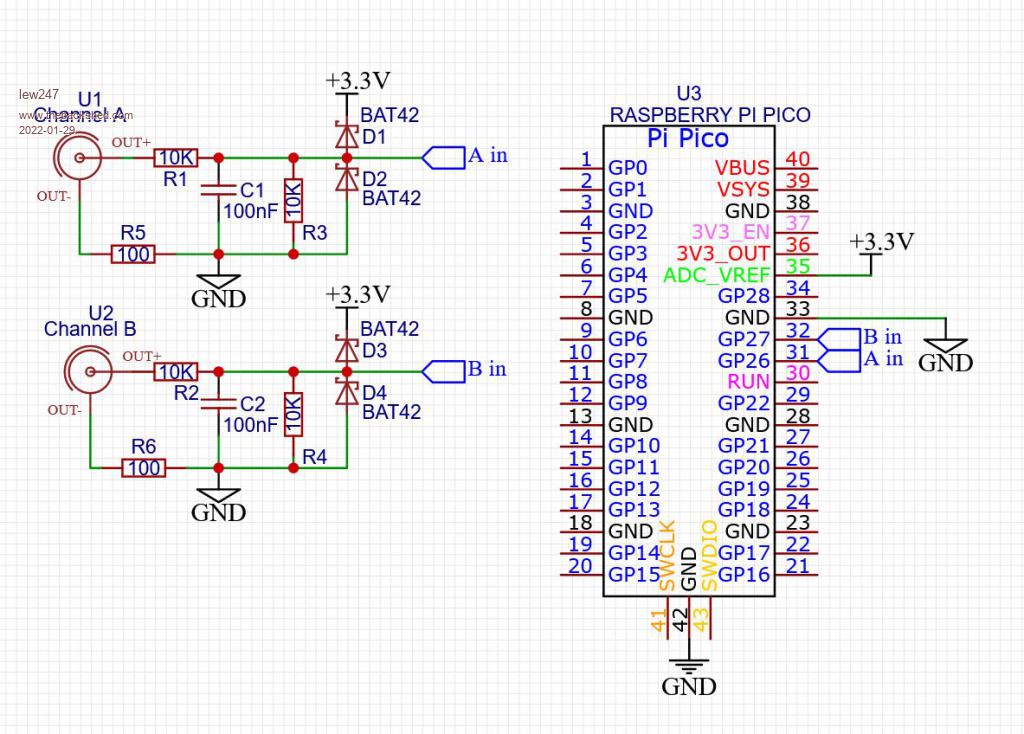 |
||||
| matherp Guru Joined: 11/12/2012 Location: United KingdomPosts: 11098 |
The maximum ADC sampling speed of the RP2040 is 500KHz. This is independent of the processor clock speed (RP2040 manual) Edited 2022-01-29 01:52 by matherp |
||||
| hitsware2 Guru Joined: 03/08/2019 Location: United StatesPosts: 738 |
How does that translate to usable bandwidth ? my site |
||||
| Mixtel90 Guru Joined: 05/10/2019 Location: United KingdomPosts: 8682 |
If you want higher voltage inputs then you *need* a voltage divider. It's how you generally reduce voltages. :) Note that ztoti's circuit is using op-amps with both positive and negative supplies. This allows the waveform to be both positive and negative relative to gnd e.g. AC supplies and signals. I'd recommend that you also put a 3V reference like the LM4040-3V0 on the REF pin then use OPTION VCC 3.0 and treat your ADC inputs as 0-3V. You'll get a more accurate and stable reading. Mick Zilog Inside! nascom.info for Nascom & Gemini Preliminary MMBasic docs & my PCB designs |
||||
| hitsware2 Guru Joined: 03/08/2019 Location: United StatesPosts: 738 |
This One ? Edited 2022-01-29 02:37 by hitsware2 my site |
||||
| ztoti Regular Member Joined: 27/10/2011 Location: CanadaPosts: 65 |
Yes that one, I didn't check Mouser. Thank you. Whole PICO cost $5.5 CAD, just PIC32 cost $12 CAD https://www.digikey.ca/en/products/detail/raspberry-pi/SC0915/13624793 Funny, right?  |
||||
| phil99 Guru Joined: 11/02/2018 Location: AustraliaPosts: 3086 |
@lew247 C1 & C2 will reduce noise at the expense of bandwidth. CRO voltage dividers usually have trimmer capacitors across R1 & R2 to compensate for input capacitance. To get maximum bandwidth you need to form a capacitive voltage divider equal to the resistive one. |
||||
| PeterB Guru Joined: 05/02/2015 Location: AustraliaPosts: 667 |
G'Day All On the subject of voltage dividers, "real" probes have an adjustable capacitor to balance stray capacitance at the DSO input. The idea is you connect the probe to a good square wave and adjust to show an equally good square wave. I wish it had been possible to get a DSO for $20 when I was a lad so enjoy it now you can. Peter I was a bit slow there  Edited 2022-01-29 09:37 by PeterB |
||||
| hitsware2 Guru Joined: 03/08/2019 Location: United StatesPosts: 738 |
I wish I could now get a flat panel display o'scope that worked like the CRT scopes from back then .... my site |
||||
| robert.rozee Guru Joined: 31/12/2012 Location: New ZealandPosts: 2498 |
happened upon this: https://www.eevblog.com/forum/testgear/pi-pico-oscilloscope/ perhaps something could be done with an external ADC and the pico's PIOs? it would not be a job for mmbasic, as one really needs close to the full RAM as a capture buffer. but if 25MS/s could be achieved across 8 bits, that would be pretty usable even if shared across 2 8-bit analog channels to give a 12.5MS/s sampling rate. addendum: what if mmbasic was just used for the UI, and ran entirely from flash? it would be slow, but may be adequate to build the user interface with. when capturing, control would be passed to a small/fast capture routine that was RAM resident. cheers, rob :-) Edited 2022-01-29 13:40 by robert.rozee |
||||
| Mixtel90 Guru Joined: 05/10/2019 Location: United KingdomPosts: 8682 |
You only need to capture and store a screen width's of values. So, using a 800x600 display at full screen size that's only 800 words of storage, assuming you use the full 12-bit range of the PicoMite's ADC. If you can capture 1600 words that's better as you can zoom x2 on the screen. You can capture the values into an array then display them to allow the lowest CPU load. Rinse and repeat. :) The input should have 1M input resistance to work with "real" probes. Any voltage divider should match that. e.g. 820k / 180k. A small trimmer capacitor across the 820k would give some high end compensation, even better with a second cap across the 180k. Then straight into a non-inverting buffer. This will usually give you the highest bandwidth that the op amp can manage. If you fancy an attenuator that's a bit beter, this looks promising. The input should be able to swing both positive and negative to be able to drive the ADC over its full range - and stay within the op-amp's output range. Consequently you'll probably need a minimum of +/- 5V for the op amp supplies as it's unlikely that you'll find a good one that can reach its supply rails. (I like your circuit, ztoti! It does all the important things. Might be worth a better op amp though, even if you have to go for higher supply rails.) Remember that most 'scopes only accept about 50V maximum on the input to stay linear. After that attenuation is done by external probes. There's no need to aim for more than this. For a PicoMite with a 3V reference a 30V maximum would seem to make sense to me. Mick Zilog Inside! nascom.info for Nascom & Gemini Preliminary MMBasic docs & my PCB designs |
||||
| hitsware2 Guru Joined: 03/08/2019 Location: United StatesPosts: 738 |
I think an external FLASH ADC wired to a MMBasic parrallel PORT would work well .....Maybe ? my site |
||||
| robert.rozee Guru Joined: 31/12/2012 Location: New ZealandPosts: 2498 |
the CA3306 ADC is a possible candidate, though the part is 25 years old now! i'm sure there is something newer that is 8-bit. out-of-the-box MMbasic is way too slow to capture data at a useful (for an oscilloscope) rate, and takes up too much of the scarce RAM. with any digital oscilloscope memory depth increases the usefulness considerably. 1) 10MS/s, giving a useful bandwidth of a few MHz, is achievable according to the earlier link to the eevblog thread. while not cutting edge, 10MHz is enough to do quite a few things. 2) by running MMbasic entirely from flash (both the user program and the interpreter), the better part of 240kB of RAM is then available for data collection, giving 120kpts per channel with 2 channels. literally, MMbasic can be halted while acquiring data. 3) MMbasic is just there to allow the user to build their own UI, cut down for this specific purpose. it could be called "OscilloMite MMbasic". could make a neat SC project! cheers, rob :-) Edited 2022-01-30 02:12 by robert.rozee |
||||
| Mixtel90 Guru Joined: 05/10/2019 Location: United KingdomPosts: 8682 |
A lot depends on what you want. If you want to examine the edges of 20MHz clock signals then you'll pay proper money for a "proper" scope. If you are happy with audio frequencies and not too fussy about doing THD measurements with it then a scope based on a PicoMite and MMBasic is probably fine. I wouldn't bother with an external 6-bit DAC when the internal (and not *that* much slower) DAC is 12-bits. You're still going to have to process the readings. Yes, you could probably do all sorts of things building a fancy analogue PCB and using the PicoMite purely as a controller, but if you're going to go down that path just spend the money on a Picoscope and plug it into a USB socket on your PC. You'll get far better results and you won't be tearing your hair out. Mick Zilog Inside! nascom.info for Nascom & Gemini Preliminary MMBasic docs & my PCB designs |
||||
| hitsware2 Guru Joined: 03/08/2019 Location: United StatesPosts: 738 |
External "FLASH" ! How long per reading is the built in ADC ? For my purpose (emulating a CRT), I would try that approach . my site |
||||
| Page 1 of 3 |
|||||
| The Back Shed's forum code is written, and hosted, in Australia. | © JAQ Software 2026 |
