
|
|
Forum Index : Microcontroller and PC projects : I 'mite not fit anything else on - SSD1963/PicoMite backpack
| Author | Message | ||||
| Mixtel90 Guru Joined: 05/10/2019 Location: United KingdomPosts: 8911 |
  I've ordered some sample boards. Should be fun. :) Mick Zilog Inside! nascom.info for Nascom & Gemini Preliminary MMBasic docs & my PCB designs |
||||
| thwill Guru Joined: 16/09/2019 Location: United KingdomPosts: 4369 |
Jesus wept, very pretty. But in the words of the Cat, "What is it?" and why would I want one except for the sadistic pleasure of mounting the most silicon possible on the smallest amount of fibreglass  . .Best wishes, Tom Edited 2022-02-06 21:37 by thwill MMBasic for Linux, Game*Mite, CMM2 Welcome Tape, Creaky old text adventures |
||||
| Mixtel90 Guru Joined: 05/10/2019 Location: United KingdomPosts: 8911 |
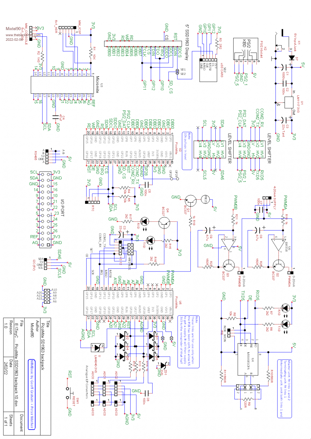
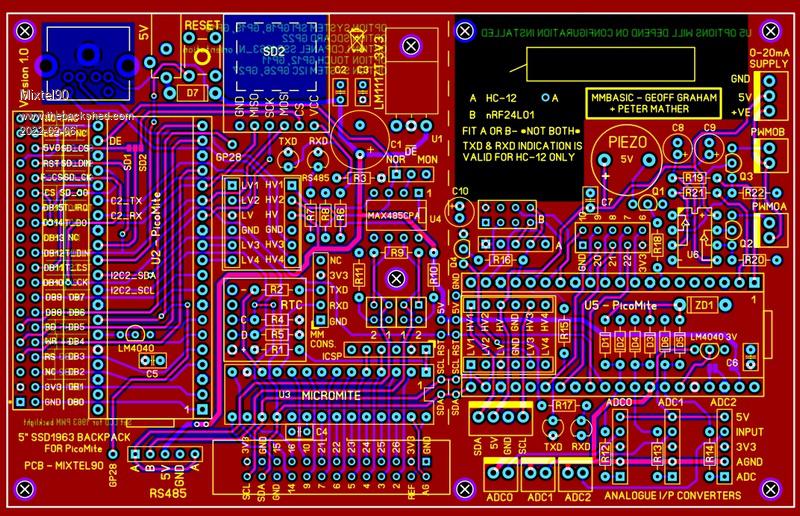
Well... yeah... it's a "Topsy" board. It started off with the RS485 version of the SSD1963 adapter. The problem with all those is that of stability - there are no fixing points in the midddle. I've put a hole over a blank-ish area of the display pcb so something like a rubber foot or nylon spacer can be fitted there, but it doesn't stop the adapter swinging backwards - it's depending purely on two corner holes of the display. The answer is to make it a full size board. But what do you do with all that empty space? The PicoMite has very few pins left when it's connected to the SSD1963. I'd used 3 for the RS485 COM port and 2 for the I2C with the RTC and Micromite on it. That only leaves 1. So it has to be something on the I2C bus. Why not another PicoMite? * You could give that the slog of the wireless stuff to handle and just get yes/no and status messages to/from the main PicoMite. That opens up the possibility of using the nRFL2401 which needs a fair bit of code but runs its own network. This module deserves more attention anyway. * So, while we're at it, we have 3 12-bit analogue inputs. Make them convertible so any value of potential divider or current shunt or even amplifier can be used. * A couple of PWM outputs can be used. We can accept current inputs now, so make them 0-20mA current outputs, which are used a lot for industrial control. * a buzzer would be nice, especially with a touch-screen. :) * We are using the RS485 version as a base, so we haven't got the 5V I2C. It only needs a level shifter so tuck that away underneath the PicoMite. :) So basically you have a 3-processor system linked over I2C. You can do whatever you like with that. :) Bits you don't like or need can simply be left off - very little is interdependent. After all that, make the board splittable. The RS485 half is more or less as before. Just a couple of tracks extended. The new half has no regulator, but a couple of links allows you to feed it with 5V and switch the PicoMite SMPS back on. There are spare pins that I've not managed to route out. I've not managed to fit open loop detection in on the 0-20mA current loops (or make them high level sourced :( ). I couldn't get stereo sound as that would need more pins on the main PicoMite. However, if someone wanted to sacrifice the RS-485 it could be done with some fiddling and a piggyback board, I suppose. Edited 2022-02-06 22:16 by Mixtel90 Mick Zilog Inside! nascom.info for Nascom & Gemini Preliminary MMBasic docs & my PCB designs |
||||
Grogster Admin Group Joined: 31/12/2012 Location: New ZealandPosts: 9975 |
Very nice "Tight" layout.  You've got the hang of Sprint Layout now, haven't you!  Smoke makes things work. When the smoke gets out, it stops! |
||||
| Mixtel90 Guru Joined: 05/10/2019 Location: United KingdomPosts: 8911 |
It's fun and it helps keep me out of mischief. :) Your library has been an enormous help, thanks once again. :) Something I did that may be useful: I did a macro of just the PicoMite GP numbers in tiny text and a pad on pin 1 for location. I can put that on the board with a normal macro overlapping in the same position. Once I've finished, just delete the pin numbers macro and they all disappear like magic. It can also be put back very easily, of course. Mick Zilog Inside! nascom.info for Nascom & Gemini Preliminary MMBasic docs & my PCB designs |
||||
| Volhout Guru Joined: 05/03/2018 Location: NetherlandsPosts: 5931 |
Hi MIck, You did it, you created a E100 (micromite extreme 100) in recent silicon. Volhout PicomiteVGA PETSCII ROBOTS |
||||
| Mixtel90 Guru Joined: 05/10/2019 Location: United KingdomPosts: 8911 |
Lol! :) I never looked at it that way. :) I can see it being a great toy though... All three 'mites can be doing their own thing at the same time, synchronising over I2C. If you connect it to chained I2C expander modules and connect the IRQ line to GP28 you can get more 'mites joining in the fun. lol Mick Zilog Inside! nascom.info for Nascom & Gemini Preliminary MMBasic docs & my PCB designs |
||||
| The Back Shed's forum code is written, and hosted, in Australia. | © JAQ Software 2026 |
