
|
|
Forum Index : Microcontroller and PC projects : PicoMite LEO - for 37 Sensor Kit
| Author | Message | ||||
| Mixtel90 Guru Joined: 05/10/2019 Location: United KingdomPosts: 8913 |
I got a little bogged down with designing a PicoMite-based PLC the other day when I hit a bit of a snag. So I started another little project just to see what I would come up with. This started with an attemp to fit as much as I could of a PicoMite VGA into the smallest possible space, but it changed direction and became an experimenters board to use with the 37 sensor kit. I also threw in the JDY-40. :) This is basically a PicoMite VGA but with most of the remaining I/O used for onboard stuff. It allows you to plug in (one at once) modules from the kit directly, with the exception of the joystick and the pouring light thing (which uses two modules). Those can be used if yo use Dupont leads with them as all the signals are there. GP26 is doing double duty as both an analogue input and digital I/O. The GND-5V-Signal devices do get 5V as the signal goes via a level shifter. 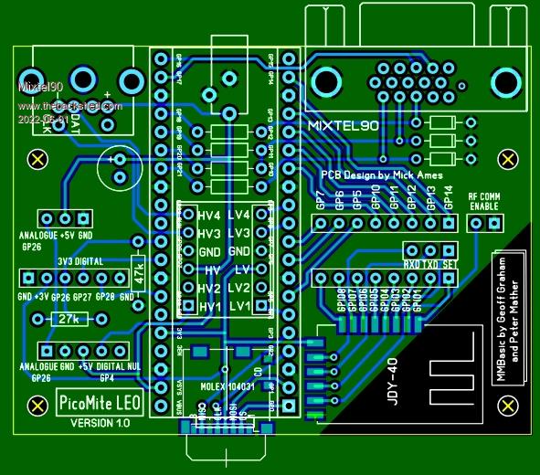 The JDY-40 has its I/O pins connected to a female header, opposite 8 Picomite GP pins so they can be directly linked using a strip of stripboard with male headers. The TXD, RXD and SET pins are on another 3-way female header that can be linked to GP ins to reprogram the JDY-40 or use it as COM. CS is on a link so it can be disabled. All in 72mm x 54mm. :) This isn't designed to go in a case - it's for experimenting. The holes allow for little pillars to be used to keep it above the table. I'll probably not make this, but if anyone is interested I'll post the gerbers. Mick Zilog Inside! nascom.info for Nascom & Gemini Preliminary MMBasic docs & my PCB designs |
||||
| lizby Guru Joined: 17/05/2016 Location: United StatesPosts: 3788 |
Nice. Can you explain further the use of the JDY-40 wifi serial module? PicoMite, Armmite F4, SensorKits, MMBasic Hardware, Games, etc. on FOTS |
||||
| Mixtel90 Guru Joined: 05/10/2019 Location: United KingdomPosts: 8913 |
The default is for it to work as a transparent half-duplex data link at 9600 baud. It will default to full power on channel 1. With CS low, just squirt data into one and it comes out of any others nearby. You don't need to do anything else. You can change the transmit power, channel number etc. using AT commands. There is a reasonable manual available on the web. The device will draw about 24mA in receive mode and 40mA while transmitting. If CS is high and it's not transmitting then the standby current is only about 5uA. Bit control mode: CS is actually a switch that allows it to run continuously. In bit control mode CS is high. Note that all bits have to be input or output - you can't mix and match them. This is a lovely mode. :) You don't need a processor - it's all done on the module. Mick Zilog Inside! nascom.info for Nascom & Gemini Preliminary MMBasic docs & my PCB designs |
||||
| Volhout Guru Joined: 05/03/2018 Location: NetherlandsPosts: 5947 |
Hi Mick, I have been watching your energy in creating picomite platforms and I am stunned by your energy. Some of your creations are not in my league, but this one actually is quite nice. Not that I own any of the 37 sensor boards, but this one contains the minimum set of components for the platform, in combination with a lot of IO. Never heard of the JDY40 but I assume it is some kind of ESP8266 alike board with some extra IO. The power usage is also acceptable. In essence... 1+ for LEO.... PicomiteVGA PETSCII ROBOTS |
||||
| Mixtel90 Guru Joined: 05/10/2019 Location: United KingdomPosts: 8913 |
I felt the urge to revisit this design. Same size board, but dropped the 37 sensor kit sockets, made the JDY-40 serial port only, added a GPIO port and Volhout's improved audio filter. I called it the Maxi version for no apparent reason. :) 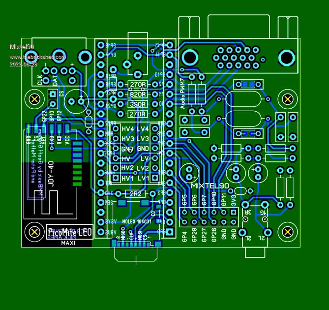 Mick Zilog Inside! nascom.info for Nascom & Gemini Preliminary MMBasic docs & my PCB designs |
||||
| Mixtel90 Guru Joined: 05/10/2019 Location: United KingdomPosts: 8913 |
The manual for the JDY-40 is here (link to PDF) Mick Zilog Inside! nascom.info for Nascom & Gemini Preliminary MMBasic docs & my PCB designs |
||||
| The Back Shed's forum code is written, and hosted, in Australia. | © JAQ Software 2026 |
