
|
|
Forum Index : Microcontroller and PC projects : PicoStick VGA
| Page 1 of 2 |
|||||
| Author | Message | ||||
| Mixtel90 Guru Joined: 05/10/2019 Location: United KingdomPosts: 8911 |
Ok, I promise I'll sort out some way of finding my PCB designs more easily. :) However, in the meantime I got a bit creative after seeing one of those little USB PCs. I thought, what would the PicoMite version look like? So the PicoStick VGA was born... It's 33mm x 52mm (should be able to get 3 out of a 100x100 board, with JLCPCB notching them). Construction would be fun, having to fit through-hole components then trim their leads very flat so that something else can be mounted on the other side. The PS/2 socket has it's tabs cut off so that the shell can be made surface mount. Power is via the PicoMite USB only (VBUS powers the keyboard). 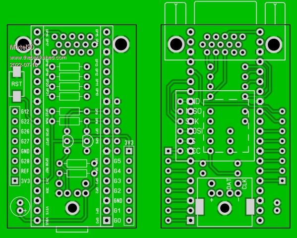 Apologies for leaving off the linear reg, audio filter, stepper motor driver, GPS, RTC, RS485 etc. Space was a bit tight. ;) Mick Zilog Inside! nascom.info for Nascom & Gemini Preliminary MMBasic docs & my PCB designs |
||||
| pwillard Guru Joined: 07/06/2022 Location: United StatesPosts: 341 |
Good design. I like it. |
||||
| vegipete Guru Joined: 29/01/2013 Location: CanadaPosts: 1180 |
Unless you are specifically trying for minimal size, I would stretch the board to 66 (or 67) mm long. Four would fit on a standard 100x100 pcb, with a 33x33 sea-of-holes left in the corner. Maybe shrink the width slightly so there is room for butchering the boards apart, for those without shears. A row of the smallest allowable holes along the separation line would help with snapping them apart. I also like to prevent the copper fill areas going right to the cut edge - I've often seen the solder mask flake off from the copper at the cut. Visit Vegipete's *Mite Library for cool programs. |
||||
| Mixtel90 Guru Joined: 05/10/2019 Location: United KingdomPosts: 8911 |
I didn't want to get it too long, Pete, in case I decided to do a version for plugging directly into the VGA port of a monitor. At that point it was a minimum size exercise and it didn't have GPIO pins. It was only later that I figured that I may as well do it like this. :) That's also why it hasn't got my usual barrel jack on it - I figured that a USB socket on the monitor would be used to power it. I don't think JLCPCB need much space between boards for grooving them - it takes up less space than drilling holes or slots and is much neater. The only problem is that you can't get 4 on a cheap board if they are grooved, but not many people are going to want 15 of them, never mind 20 as minimum orders. :) I'm not even sure if they charge extra for grooving them. As usual, it's just an idea in progress. :) Mick Zilog Inside! nascom.info for Nascom & Gemini Preliminary MMBasic docs & my PCB designs |
||||
| lizby Guru Joined: 17/05/2016 Location: United StatesPosts: 3784 |
How do you specify a groove, Mick? PicoMite, Armmite F4, SensorKits, MMBasic Hardware, Games, etc. on FOTS |
||||
| pwillard Guru Joined: 07/06/2022 Location: United StatesPosts: 341 |
JLCPCB has a section on their website that explains the VGROVE... you also need to add extra blank space past the groove area. |
||||
bigmik Guru Joined: 20/06/2011 Location: AustraliaPosts: 2981 |
Gday All, I used to get Vee groove done quite often but JCL have good prices for smaller PCBs so I dont need to panelise up as much. But for the record I have had gaps of approximately 1mm from the nearest track to the V-Groove section. If you need an exact figure I would have to look them up. I had one design (My NanoMite) that had a 6 x 6 layout (36 boards in total) on a 100mm x 100mm panel, the PCB is 15mm x 15mm which gives them room to add manufacturing holes in the excess edges of a 100mm panel Regards, Mick EDIT *** Here is a picture of some I sent to MicroBlocks (Are you still around Jean?) Unfortunately I dont have a full panel anymore but I probably have a block of 4 I can take a better picture of. Mick Edited 2022-07-16 12:42 by bigmik Mick's uMite Stuff can be found >>> HERE (Kindly hosted by Dontronics) <<< |
||||
| Solar Mike Guru Joined: 08/02/2015 Location: New ZealandPosts: 1213 |
For small quantities of multiple pcb's like that fitting within 100 x 100mm size, I get them made in 1mm thickness and just cut them out using a large pair of tin-snips, easy as bro. Cheers Mike |
||||
| bigmik Guru Joined: 20/06/2011 Location: AustraliaPosts: 2981 |
All, I forgot to upload the picture 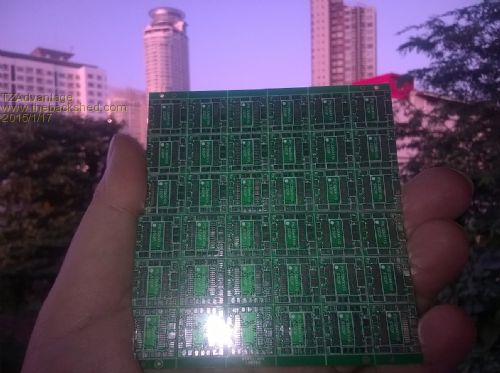 Mik Mick's uMite Stuff can be found >>> HERE (Kindly hosted by Dontronics) <<< |
||||
| Mixtel90 Guru Joined: 05/10/2019 Location: United KingdomPosts: 8911 |
@Lizby Using Sprint Layout, I don't know. :) I'd guess at leaving a gap in the groundplane on both sides with a thin line on the O layer where the groove is wanted. I've never tried it, and SL hasn't got a special layer or anything - not even a comments layer. Mick Zilog Inside! nascom.info for Nascom & Gemini Preliminary MMBasic docs & my PCB designs |
||||
| Mixtel90 Guru Joined: 05/10/2019 Location: United KingdomPosts: 8911 |
Erm... it grew just a little. Now about 62mm x 31mm but includes a RTC. 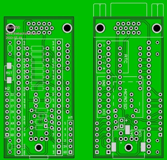 � Power comes from USB socket, with 5V from VSYS, which also has a diode from a 2-pin header to power it from an external source. You could leave off the VGA and PS/2 sockets and use mounting pillars, loading ordinary PicoMite firmware, to make a stand-alone controller. H1 includes enough pins to get a I2C, COM or SPI port, H2 includes the ADC inputs and a couple of digitals. H1 and H2 are on a sensible 2.54mm mm grid, so it would be possible to make a piggy-back board over the top of the PicoMite. I think I'll do one with the male VGA connector, to plug directly into a monitor. It might make a useful little development device without cluttering the table up. Or you can run MMB4W, of course. :) Edit: Just squeezed in a WS2812B on GP15. �:) Edit Edit: I've just realized - no need to do a direct plug-in version. Just mount a DB15M on the same side as the PicoMite instead of a DB15F on the other side. :) . Edited 2022-07-18 17:57 by Mixtel90 Mick Zilog Inside! nascom.info for Nascom & Gemini Preliminary MMBasic docs & my PCB designs |
||||
| Mixtel90 Guru Joined: 05/10/2019 Location: United KingdomPosts: 8911 |
Construction Pack now available. Very slightly different to the above. This might be a good one for those looking for a small format board without resorting to surface mount. Construction pack.zip . Mick Zilog Inside! nascom.info for Nascom & Gemini Preliminary MMBasic docs & my PCB designs |
||||
| lizby Guru Joined: 17/05/2016 Location: United StatesPosts: 3784 |
I put together this great little PicoStickVGA board:  I used the resistors as specified, but got the same tan-ish white as with the PicoPear (posted recently), so maybe it's my monitor:  The text on this image shows that I was able to fix the offsetting of the image to the left--there was a horizontal shift adjustment possible on my monitor. Same code as before: mode 2 dim integer i,j,k,c,x,y=1 dim integer xx=mm.hres-1,yi=mm.vres/8 for i=0 to 1 for j=0 to 1: for k=0 to 1 c=rgb(i*255,j*255,k*255) box x,y,xx,yi,,c,c y=y+yi next k next j next i I ran into two minor problems building the board: 1) I misunderstood where the right ends of R3 and R5 were, so soldered them into the holes for the external power (which I didn't intend to use); I noticed it and fixed it before powering it on; and 2) the holes for the pin header for the DS3231 module are smaller than the other holes--I had to file down the male header pins to make them fit. I haven't yet tried keyboard, RTC, or SD card. Will soon. PicoMite, Armmite F4, SensorKits, MMBasic Hardware, Games, etc. on FOTS |
||||
| Martin H. Guru Joined: 04/06/2022 Location: GermanyPosts: 1459 |
in theory your resistor for Red is a little low so red is a little to high. All resistors are ~270Ohm (Both Green in Parllel are about 264Ohm) With 75 R VGA input impedance the Voltage of each Chanal should be ~1.45 Volt on each Color. Looks that Red is a little higher so try to add 10 Ohm to R9 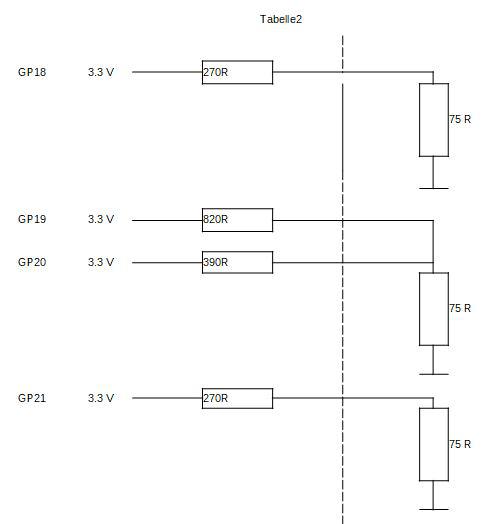 Edited 2022-08-25 02:45 by Martin H. 'no comment |
||||
| lizby Guru Joined: 17/05/2016 Location: United StatesPosts: 3784 |
Thanks for the suggestion. I'll live with tan for now. It would be good if the help file had the OPTION SYSTEM setups. I figured out OPTION SYSTEM I2C GP12,GP13 but got RTC not found (or something like that). Turns out "-" on the RTC header is not connected to anything. After wiring it to ground, I have the RTC set up and working through power cycling (after RTC SETTIME). But the OPTION SYSTEM SPI for the SD card has me baffled. Upside down and backwards images of a two-sided board have left me only confused. What should the OPTION be? PicoMite, Armmite F4, SensorKits, MMBasic Hardware, Games, etc. on FOTS |
||||
| Mixtel90 Guru Joined: 05/10/2019 Location: United KingdomPosts: 8911 |
I do like it when people test my PCB designs. That looks great! �:) I'd missed a GND on that pin. Sorry. I'll sort that out. OPTION SDCARD GP6, GP11, GP7, GP10 Martin: If he's followed the circuit he has the recommended values. Edited 2022-08-25 04:51 by Mixtel90 Mick Zilog Inside! nascom.info for Nascom & Gemini Preliminary MMBasic docs & my PCB designs |
||||
| lizby Guru Joined: 17/05/2016 Location: United StatesPosts: 3784 |
Thanks, Mick--that did it. SD card is working. Real PS/2 keyboard is also working. Very nice little board, thank you. PicoMite, Armmite F4, SensorKits, MMBasic Hardware, Games, etc. on FOTS |
||||
| phil99 Guru Joined: 11/02/2018 Location: AustraliaPosts: 3291 |
@Martin H. A trap when calculating Pico output currents or voltages is the Pin resistance (40 to 50 ohms) is in series. So the VGA resistors need to be lower than you expect. With LCD monitors (and most CRT's) a little overdrive does no harm and ensures a pure white when all 4 outputs are high, even if the resistor values aren't exactly right or perfectly matched. The clipping diodes aren't needed as the monitors A-D converters do the clipping for you. All monitors I have tested can tolerate an input of at least 1.5V without ill effect. @Lizby Your monitor blues appear to be a lack of blues! Does your monitor have a "Night Mode"? That would reduce the blue content. To see if the problem is at the Pico end measure the voltages on the VGA socket pins. With MODE 2 CLS RGB(WHITE) Using a multimeter I get 0.55V on red and blue and 0.57V on green. These are lower than you get on a CRO because of the blanking intervals. The important point is that red and blue should be the same. The resistors I am using are:- Red = 220R Green H = 330R Green L = 680R Blue = 220R 'Generate Colour bars. RGB(1,2,1) 4 bit Mode 2 Dim integer i, R=0, G=0, B=1 For i=1 To 301 Step 20 �If i > 155 Then : R=255 : Else : R=0: EndIf �B=(Not B)*255 �Select Case (i Mod 160) � Case 1 : G=0 � Case 41 : G=64 � Case 81 : G=128 � Case 121 : G=255 �End Select �Box i,1,20,240,1,RGB(R,G,B),RGB(R,G,B) Next Or modifying the previous one to also get all 16 colours. mode 2 dim integer i,j,k,c,x,y=1 dim integer xx=mm.hres-1,yi=mm.vres/16 for i=0 to 1 � for j=0 to 3 � � for k=0 to 1 � � � c=rgb(i*255,j*64,k*255) � � � box x,y,xx,yi,,c,c � � � y=y+yi � � next k � next j next i Edited 2022-08-25 18:32 by phil99 |
||||
| JohnS Guru Joined: 18/11/2011 Location: United KingdomPosts: 4335 |
The BOM refers to: Micro USB socket module incorporating pull-up resistors and decoupling capacitors (ebay - see pic) Is the pic missing? John |
||||
| Mixtel90 Guru Joined: 05/10/2019 Location: United KingdomPosts: 8911 |
It's the pic called s-1286d.jpg. It's mounted with the socket towards the PCB. This is a very nice little module, it just seems odd that it's "upside down" - it comes with the header pins ready soldered. 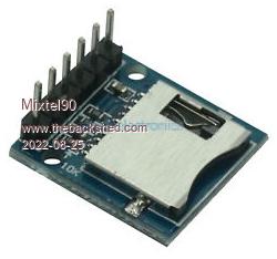 Edited 2022-08-25 21:27 by Mixtel90 Mick Zilog Inside! nascom.info for Nascom & Gemini Preliminary MMBasic docs & my PCB designs |
||||
| Page 1 of 2 |
|||||
| The Back Shed's forum code is written, and hosted, in Australia. | © JAQ Software 2026 |
