
|
|
Forum Index : Microcontroller and PC projects : PicoMuP and Mini Pico-PC
| Author | Message | ||||
bigmik Guru Joined: 20/06/2011 Location: AustraliaPosts: 2981 |
Hi All, I have been working on a board for the Pico-Pi, partly because of the difficulty in obtaining Microchip parts but mostly because of the price, ready availability and the features that the Pico-Pi has to offer. Bang for buck they are extremely hard to beat. The PCBs are 3 part, as follows: PicoMuP (50mm x 50mm) 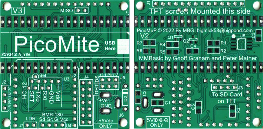 PicoMuP is the main Board for both the TFT and VGA versions of Pico-MMBasic. The main board is designed to mount onto the back of an SPI 14pin TFT module and has support for the following features: Header for 14pin SPI TFT display DS3231/2 RTC chip Header for DS18B20 Header for DHT22 HC12 wifi Serial ESP8266-Mini (aka NodeMCU D1-mini) internet wifi BMP180 header (barometric pressure and temperature) Expansion header for Pico-KB-VGA 2.1mm Barrel Jack for 5Vdc centre +ve power input. Pico-KB-VGA (20mm x 50mm) 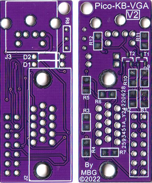 Pico-KB-VGA, as its name suggests is a plug in PCB that has the circuitry for the VGA output and PS2 keyboard input. There is a 14pin (2x7) header that connects Pico-KB-VGA to PicoMup. PicoMuP-Extender (50mm x 28mm) 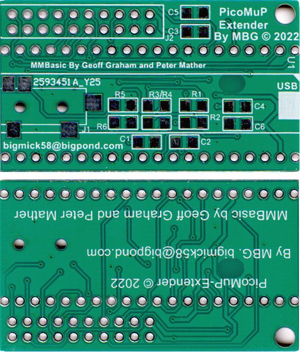 PicoMuP can be used with BOTH the TFT and the VGA versions and provides a 20pin header with most GPIO plus 5V, 3v3 and GND. for connection to external devices. The PicoMuP-Extender is designed to solder directly over the top of the Pico-Pi board via male header pins, This allows it to sit low enough that the PicoMuP-KB-VGA can `swing' over the top of it and not foul it also provides a 3.5mm stereo Audio jack for sound. Anyway, My pet project has been to try to create a mini Pico-PC using the above mentioned PCBs and create as small as possible Pico-PC. I found these nifty (and dirt cheap) boxes on Aliexpress for about $3AU for 2 shipped, crikey I couldn't pay the postage to the next door neighbour for that price. 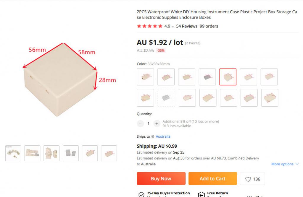 It was a tight (Read that as VERY TIGHT) fit to get it all in but this is the final result. 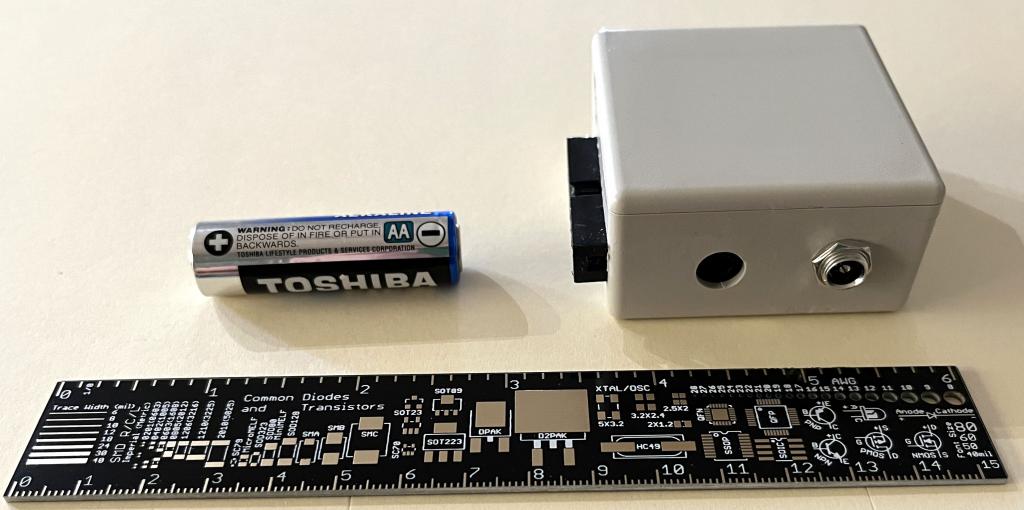 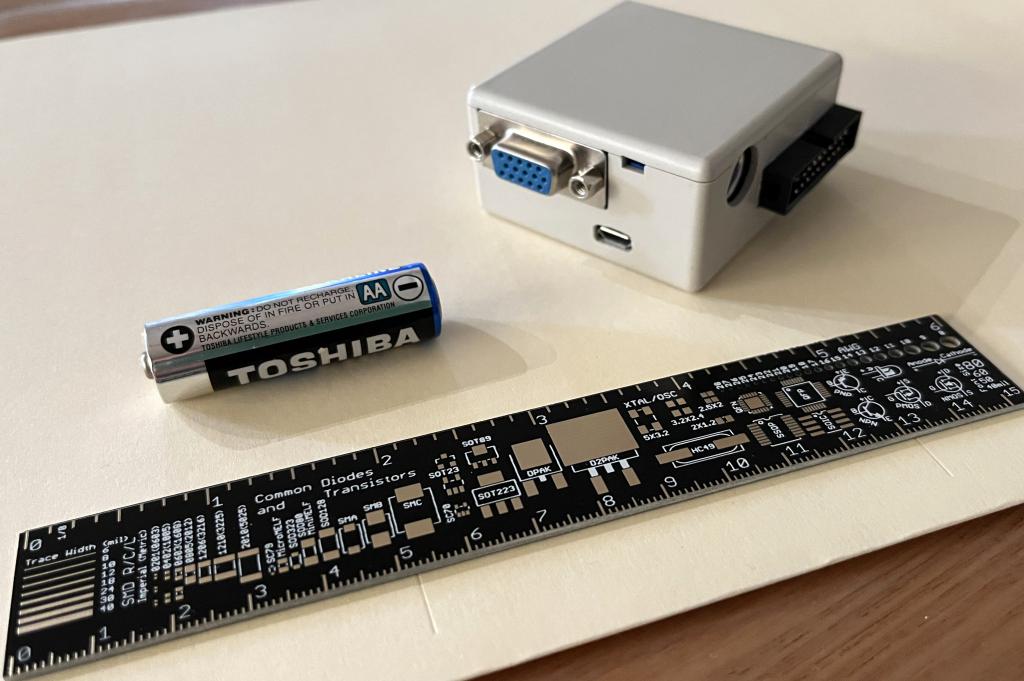 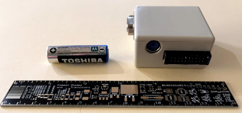 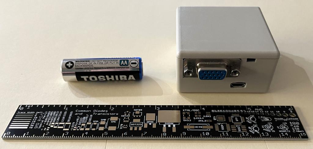 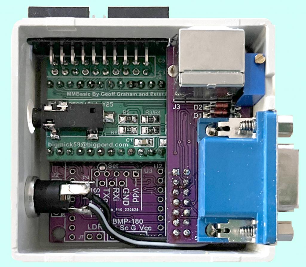 I designed these boards in conjunction with AndrewG primarily for our own use, due to the chip shortage of the PICs. I have been gradually getting out of selling boards etc to enjoy my retirement, however if there is any interest in them please PM or email me and we can discuss further based on your requirements. I have a few earlier versions of PicoMuP (you will note the latest is Ver. 3) that have very minor issues that can easilly be overcome and I can offer some of those at a pretty cheap `token' I would say Beer money but a beer isnt so cheap these days. Anyway if there is any interest you know how to contact me. I hope this long winded post hasnt been too boring. Kind Regards, Mick EDIT *** As can be seen in the pictures the Pico-PC is a little larger than a AA battery. Also I do not `yet' have a manual for the PCBs and may not end up doing one as the builds are fairly self explanatory, I do have all schematics and parts overlays ov course and can supply them. MBG Edited 2022-07-27 11:12 by bigmik Mick's uMite Stuff can be found >>> HERE (Kindly hosted by Dontronics) <<< |
||||
| Rickard5 Guru Joined: 31/03/2022 Location: United StatesPosts: 463 |
 Shoot me a Quote for the set they look like fun to build, and I'll Draw up some Slick 3d Printed Cases for them I may be Vulgar, but , while I'm poor, I'm Industrious, Honest, and trustworthy! I Know my Place |
||||
| bigmik Guru Joined: 20/06/2011 Location: AustraliaPosts: 2981 |
Thank You Rickard, PM sent. Regards, Mick Mick's uMite Stuff can be found >>> HERE (Kindly hosted by Dontronics) <<< |
||||
| Mixtel90 Guru Joined: 05/10/2019 Location: United KingdomPosts: 8977 |
That's a lovely job, Mick A thing of beauty! :) Mick Zilog Inside! nascom.info for Nascom & Gemini Preliminary MMBasic docs & my PCB designs |
||||
| bigmik Guru Joined: 20/06/2011 Location: AustraliaPosts: 2981 |
Hi Mick, Did you mean ME?  Sorry I couldn't help but edit your comment. Sorry I couldn't help but edit your comment.Thank you for your comment. It is honestly amazing how small it is when you actually see it. Mick (The BIG one) Mick's uMite Stuff can be found >>> HERE (Kindly hosted by Dontronics) <<< |
||||
| lizby Guru Joined: 17/05/2016 Location: United StatesPosts: 3829 |
What a neat and tidy (and powerful) package. Congratulations on fitting it all in. PicoMite, Armmite F4, SensorKits, MMBasic Hardware, Games, etc. on FOTS |
||||
| Mixtel90 Guru Joined: 05/10/2019 Location: United KingdomPosts: 8977 |
I wonder if the kit comes complete with a small hammer for getting it into the case? ;) Mick Zilog Inside! nascom.info for Nascom & Gemini Preliminary MMBasic docs & my PCB designs |
||||
| bigmik Guru Joined: 20/06/2011 Location: AustraliaPosts: 2981 |
Hi Mick, I think you need a more powerful hammer to get it in that tiny box. Once I get a few projects out of the way I will create a “how to” document on fitting it in the box. It all went really well until I tried to squeeze the header out the back. If the 20pin header is soldered to the extender board it is nigh on impossible to to get the header out the hole in the back whilst at the same time getting the extender board over the header pins on the Pico-pi (even with them cut down to bare minimum to allow the board to be soldered to the Pico-pi.) I did it but I had to open the height of the header hole about 1mm plus use a bit of ‘gentle persuasion’. In retrospect I think it might be better to put the extender onto the Pico-pi (not solder yet) then try to rock the header in from the outside and solder the pins from the top once the header is in the extender. A needle point tip would be a must. Another idea is to fit a vertical female header to the extender and then the R/A header can be popped into the female one and the opening for it can be higher up to be level with the top of the case. If I build another one I will explore these options and document the entire process so others can have Pico-PCs as well. Regards Mick Mick's uMite Stuff can be found >>> HERE (Kindly hosted by Dontronics) <<< |
||||
| The Back Shed's forum code is written, and hosted, in Australia. | © JAQ Software 2026 |
