
|
|
Forum Index : Microcontroller and PC projects : PicoMite Pin Usage - SPI and PS/2 KB
| Author | Message | ||||
| vegipete Guru Joined: 29/01/2013 Location: CanadaPosts: 1180 |
I have a couple of questions about pin usage on the PicoMite. Perusing the manual doesn't give me a clear (to me) answer. Question 1 - SPI pins: Appendix D explains setting up the 2 available SPI ports. MOSI, MISO and CLK can be configured for SPI and SPI2 separately. The pin choices allow no overlap between ports. How is this affected by OPTION SYSTEM SPI? Does this create a third SPI port? Or does the SYSTEM SPI port replace one of the 2 ports? Which one? Question 2 - PS/2 Keyboard Pins: Absolutely no way to change those pins? Could they maybe possibly be configurable? As it stands, the keyboard cannot be used with the WaveShare 3.5" display module. Thanks. Visit Vegipete's *Mite Library for cool programs. |
||||
| Mixtel90 Guru Joined: 05/10/2019 Location: United KingdomPosts: 8913 |
System SPI has to be one of the two existing hardware SPI ports of the RP2040. You can use any of the available pins that can be allocated for a particular port, so you could for example se GP0 (spi_rx), GP7 (spi_tx) and GP18 (spi_clk) with any pin for spi_cs. You can use system spi for any valid spi devices, but if you are using it for a display you obviously mustn't close it. :) Once OPTION SYSTEM SPI is set the port is open so there is no need to open and close it to use it for anything else. Note that OPTION SYSTEM SPI isn't available for the VGA firmware as there will never be a SPI display connected. The SD card SPI is a special case as it is bit-banged. As such it can use any pins. If it's on the system spi pins then they are temporarily bit-banged while the card is accessed before being returned to hardware control. I have wondered about the PS/2 pins myself. I'm guessing that they are being bit-banged in a routine that's time-sensitive and it may be difficult to use alternatives. Only a guess though. Is that display one of the awkward ones? If so it might be better to simply use a different (and better) one. Mick Zilog Inside! nascom.info for Nascom & Gemini Preliminary MMBasic docs & my PCB designs |
||||
| matherp Guru Joined: 11/12/2012 Location: United KingdomPosts: 11551 |
Yes: either as you want Lot of work as PS2 uses a H/W interrupt for the clock pin. Given the Waveshare can't even support BLIT etc (no MISO) then not worth it for this display. Better to use an ILI9488 and then you get flexible pin usage |
||||
| Mixtel90 Guru Joined: 05/10/2019 Location: United KingdomPosts: 8913 |
Thanks Peter. :) Mick Zilog Inside! nascom.info for Nascom & Gemini Preliminary MMBasic docs & my PCB designs |
||||
| vegipete Guru Joined: 29/01/2013 Location: CanadaPosts: 1180 |
So this means the SYSTEM SPI port pins must be chosen from the allowable pin groups for SPI _or_ SPI2? (No mixing and matching.) And therefor the SYSTEM SPI is assigned to SPI or SPI2 based on the pins chosen? For example, "OPTION SYSTEM SPI GP10,GP11,GP12" results in using SPI2 for the system SPI. And "OPTION SYSTEM SPI GP16,GP15,GP14" is illegal because GP16 is on the wrong channel. And further, there is no resource contention if I use that SPI port (assuming I obey CS, don't close the port, ...) while other features are enabled, such as a touch screen? For example, a command such as "received_data = SPI2(data_to_send)" won't start until the SPI2 port is available, and other access is blocked until the command completes. Visit Vegipete's *Mite Library for cool programs. |
||||
| matherp Guru Joined: 11/12/2012 Location: United KingdomPosts: 11551 |
You can't use the system SPI for any other use. It will be used for touch, LCD and SDcard as required. The other SPI channel is fully available as per any other version of MMBasic. Pins for a SPI channel must be assigned as per the the diagram in the manual all either SPI or SPI2/SP2. Of course SPI is trivial to bitbang in which case any pins can be used |
||||
| stanleyella Guru Joined: 25/06/2022 Location: United KingdomPosts: 2807 |
I thought picomite had 2 "hardware" spi. some basics say bit bang where others say software spi. I'm wiring a new picomite to another ili9341 and will check the wiring cos touch is shared with the display hardeware spi but not checked the sd card slot... too busy being happy it worked as it was join the dots construction from Geoff's site and his connection drawings. 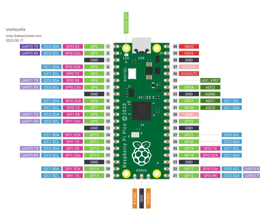 |
||||
| Mixtel90 Guru Joined: 05/10/2019 Location: United KingdomPosts: 8913 |
That diagram is, to be picky, for the Pico, not the PicoMite. :) The one in the manual is the one that you need to refer to if you want to get the names right. There are two hardware SPI ports, referred to in MMBasic as SPI and SPI2, That's to keep compatibility with other MMBasic platforms that only have a single channel called SPI. Using those means that you MUST use the pins shown on the PicoMite diagram. As I said previously, the SD card is a special case and uses bit-banged SPI. That can use any pins, they don't have to be specified for SPI. It's usually convenient (and pin-saving) to put it on SYSTEM SPI together with a LCD display and Touch though as it only uses one additional pin (for CS) then. Mick Zilog Inside! nascom.info for Nascom & Gemini Preliminary MMBasic docs & my PCB designs |
||||
| stanleyella Guru Joined: 25/06/2022 Location: United KingdomPosts: 2807 |
OK I'll use the one in the manual 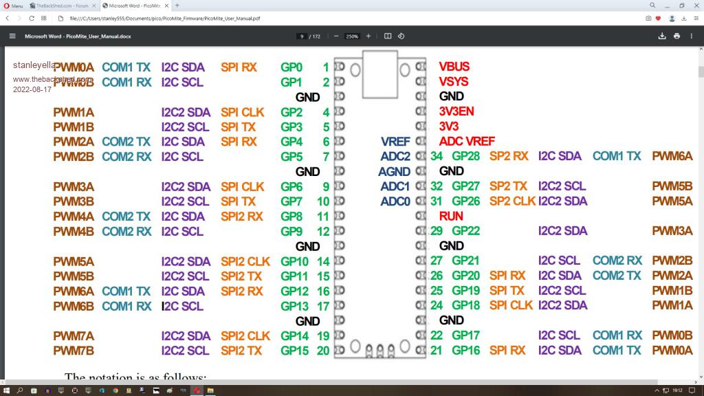 |
||||
| The Back Shed's forum code is written, and hosted, in Australia. | © JAQ Software 2026 |
