
|
|
Forum Index : Microcontroller and PC projects : physical sdcard problem in sub millimeter range - solved!
| Author | Message | ||||
| andreas Senior Member Joined: 07/12/2020 Location: GermanyPosts: 226 |
I received a new sdcard and formatted it to FAT32 because I wanted to use it within a HW-125 sdcard reader connected to a pico w. The sdcard received (right side) was exactly the same as I had already and which worked fine in the past (left side). 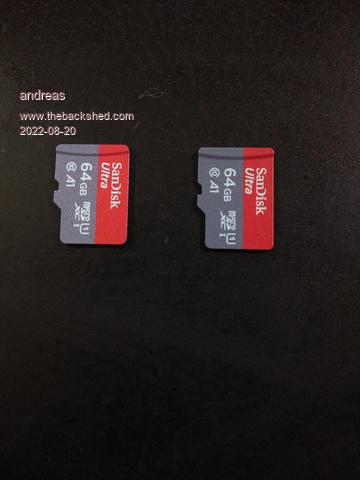 I could see both cards inserted into an adapter in my main PC, I could read and store data on both of them - the cards were ok. Then I inserted the new card in to the Pico sdcard reader HW-125 and it didn't work: ? mm.info(sdcard) -> Not present files -> Error: SD card not found Now I tried several sizes 2GB, 32GB and formats FAT32, extFAT, ext4 no success. Because the cards both worked within the PC but the new one not with the HW-125 I added a tiny red marker ("Klebepunkt" in german) to the new card (right side) to make it a little thicker - possibly only a 1/10 mm: 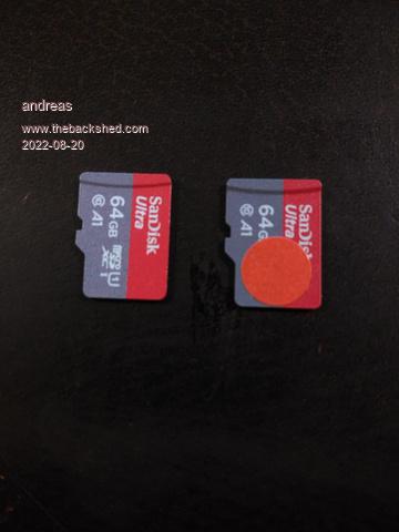 This solved the problem! Now the card works within the reader. That means the contacts within the reader had no contact to the card. The paper clip makes the card slightly thicker and the pressure in direction to the reader contacts is higher. -andreas Edited 2022-08-20 04:12 by andreas |
||||
| led-bloon Senior Member Joined: 21/12/2014 Location: AustraliaPosts: 209 |
Actually only needed one pin not to make contact, but still... Amazing job, thanks for sharing. led Miss you George |
||||
| zeitfest Guru Joined: 31/07/2019 Location: AustraliaPosts: 683 |
Excellent !!! Thank you |
||||
| andreas Senior Member Joined: 07/12/2020 Location: GermanyPosts: 226 |
Update: Because the red dot gave better results but unfortunately not perfect results (there were still "no sdcard" events) I did another modification. I added a "step up" module (2$) which generates a stable adjustable 5.00 volts out of the lower 4.22 volts of the full akku. I took VSYS of the pico (pin 39) as input for the step-up and then the 5 volts output into the card reader. Now it is really working stable. The test-procedure was an autorun programm which writes on the sdcard. After 20 seconds I switched off the "mini-pc" and put the sdcard into my PC to read the values. I repeated that several times. So my result is: Contacts have to be checked, 100 MHz cpuspeed and the sdcard voltage should be 5 volts to get a stable working sdcard. The funny thing is, that the sdcard has a buckboost chip which generates 3.3 volts from the 5V input voltage  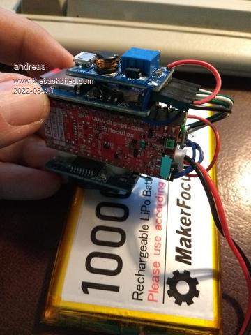 -andreas |
||||
| pwillard Guru Joined: 07/06/2022 Location: United StatesPosts: 341 |
Seems rather logical. Maybe the buck-boost has a drop-out issue due to the lower difference between input and output voltage when running at 4.22v. Edited 2022-08-21 00:05 by pwillard |
||||
| robert.rozee Guru Joined: 31/12/2012 Location: New ZealandPosts: 2533 |
hi andreas, Ā Āis the SD adapter board you are using like this one? https://www.amazon.com/AiTrip-Module-Conversion-Arduino-Adapter/dp/B07ZB9ZDHB if so, it is probably not the best choice: 1. it uses a 74LVC125A (https://www.ti.com/lit/ds/symlink/sn74lvc125a.pdf?ts=1661002662133) to buffer the signals. this really doesn't add anything useful, as the pico pins are already quite capable of driving directly into the SD card (and vice versa); 2. the board also contains (four) 3k3 series resistors at each of the 74LVC125A output pins, which will significantly slow down signals passing back and forth between the pico and the SD card. this is why you are having to throttle back the pico to 100MHz. if the board were being used with an arduino this would not be such an issue, as arduinos generally only run at 10's of MHz. for the (HW-125 and similar) schematic, see: https://www.sunrom.com/get/192293; 3. as you have discovered, you need to supply the board with at least 4.6 volts for the onboard AMS1117 regulator (http://www.advanced-monolithic.com/pdf/ds1117.pdf) to produce a clean 3v3 supply for the SD card. while the AMS1117 on its own is not a bad thing, the pico already generates a suitable 3v3 supply. you should be using an SD adapter board that contains NO series resistors (10k pullups to 3v3 are ok but not necessary), and NO buffer or level translation. it is ok for the board to contain a 3v3 regulator for the SD card's supply, but this will commit you to having to provide 4.6 volts or more from somewhere. fine if the pico is always tethered to a USB port that supplies 5v, less so if operating standalone on batteries. as an aside, if using with an arduino, the 74LVC125A is an extremely poor choice as it is NOT a level translator. it is just a bus driver, providing a higher output current but no level shift. as such, the MISO pin will be at 3v3 levels, but connected to a 5v level input on the arduino. Ā cheers, rob Ā :-) Edited 2022-08-21 00:37 by robert.rozee |
||||
| The Back Shed's forum code is written, and hosted, in Australia. | © JAQ Software 2026 |
