
|
|
Forum Index : Microcontroller and PC projects : PicoMite VGA XPerimenter
| Author | Message | ||||
| Mixtel90 Guru Joined: 05/10/2019 Location: United KingdomPosts: 8963 |
My LEO Mexi design got me thinking. My original concept was for it to be an educational board, but has too much on it really. So, how about a more minimalist design. It has to be cheap and pretty rugged yet still use the VGA monitor and PS/2 keyboard. It also needs a few GPIO pins, including the ADC ones. I've made it simple to build, I think, and kept a full size SD card as they are easily handled. The GPIO connector is flanked by two 2.5mm clear holes, the idea being that a "hat" could be fitted and screws used to to keep it in position. It might be useful to add, say, series resistors & terminal blocks for some I/O to make it more bomb-proof. I decided to keep a RTC so that file time & date info can be kept, but it's obviously optional. All the GPIO pins are uncommitted. EDIT: This PCB is 85mm x 50mm so you can get two out of a single 100x100 board and it allows for 7.5mm waste strips at the ends, so getting the PCB house to V-groove them is a definite possibility. 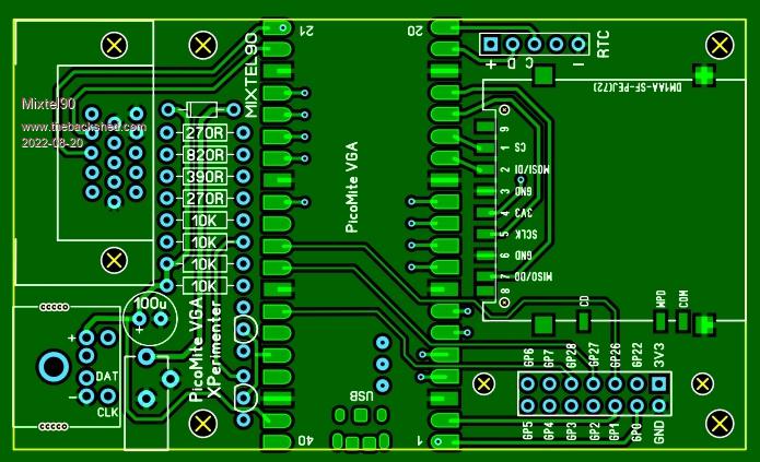 Edited 2022-08-20 05:51 by Mixtel90 Mick Zilog Inside! nascom.info for Nascom & Gemini Preliminary MMBasic docs & my PCB designs |
||||
| Volhout Guru Joined: 05/03/2018 Location: NetherlandsPosts: 5994 |
This is actually a very nice and compact design. Do you have ordering info for the VGA and PS2 connector (R&S or Farnell codes) There is one thing that could be done to improve. Put the GPIO and RTC header in the same 0.1" (1e) grid, so you could mount a "hat" that also has the I2C lines as well as the analog lines. Looks like there is 15.7e between them, or my monitor confuses me. Edited 2022-08-23 16:54 by Volhout PicomiteVGA PETSCII ROBOTS |
||||
| Mixtel90 Guru Joined: 05/10/2019 Location: United KingdomPosts: 8963 |
The connectors are, IIRC, the same as the CMM2 and PicoGAME. I'll be sorting out the usual info before long. I got waylaid by having to do necessary things rather than play. :( �I'm trying slots for the PS/2 connector this time as a space saver. That's an excellent idea. I'll try that. You can mount a "hat" anyway, but having I2C and power lines at the other end would be very useful. Possibly another "hat" fixing hole too, as "hats" can be pretty big on this board. EDIT: Yes, I can get both connectors on a 0.1" matrix, together with two new "hat" fixing holes either side of the RTC connector. It'll be fine with ordinary pad board, although the 2-row connector isn't great with strip board. The maximum "hat" size is about 65mm x 50mm if you want to stay within the PCB area. It covers the PicoMite as well as the SD card socket but that's not really a problem once the BOOTSEL button has done its work. Edited 2022-08-23 19:45 by Mixtel90 Mick Zilog Inside! nascom.info for Nascom & Gemini Preliminary MMBasic docs & my PCB designs |
||||
| Volhout Guru Joined: 05/03/2018 Location: NetherlandsPosts: 5994 |
Hi Mick, Not sure if you need separate "hat-fixing" holes. The 4 standard mounting holes can get standoffs and serve as such. As long as you get them all on 1e grid, that simplifies the "perfboard" implementation of a hat. Another thing to be desired is the wiring to the SD card (if you can manage on the 2 layer board). Currently: GP13 - MISO GP12 - CLK GP11 - CS GP10 - MOSI Desirable: GP13 - CS GP12 - MISO GP11 - MOSI GP10 - CLK This allows the use of the SD card in case the standard picomite firmware is loaded by defining the OPTION SYSTEM SPI (in other words this same board can be used with the non-VGA firmware). Not sure if it is ever used but it is simply re-wiring few pins. Maybe not a big issue. Adding GP10,11,12 to the "extended" RTC header would also allow implementation of an LCD onto the VGA Xperimenters board. Volhout Edited 2022-08-23 20:53 by Volhout PicomiteVGA PETSCII ROBOTS |
||||
| Mixtel90 Guru Joined: 05/10/2019 Location: United KingdomPosts: 8963 |
Like the LEO ideas, but a bit more so, this is designed for educational use. Plug-in hats are likely (not just liable with kids involved!) to be pulled out, which is less likely if they are secured to the board. :) The hat fixing holes are on the 0.1" grid so are easy to use if you want them. The board fixing holes are on mm centres (the board has mm dimensions) to make measurement easier. A complete assembly could easily be fitted into a robot or something without restricting access to them. I probably *could* get them onto the grid, but it would mean moving the SD card socket if I want to keep them symmetrical, which is a bit tricky. As this isn't designed to fit into a case the fixing holes will normally have feet (or very short pillars) in them. EDIT: Removed one hat fixing hole & extended RTC connector to right, now 7 male pins. Changed SD card connections to "Desired" arrangement. Brought out GP10, GP11 & GP12 to the unused pin and two new pins of the RTC connector. :) Edited 2022-08-23 21:34 by Mixtel90 Mick Zilog Inside! nascom.info for Nascom & Gemini Preliminary MMBasic docs & my PCB designs |
||||
| lizby Guru Joined: 17/05/2016 Location: United StatesPosts: 3808 |
Looking very interesting here, especially with a 2-for-1 layout with snap-able v-groove. What would it take the make the two linkable via serial? (Maybe that's something for a hat to do.) Nice, clean design. ~ Edited 2022-08-23 22:29 by lizby PicoMite, Armmite F4, SensorKits, MMBasic Hardware, Games, etc. on FOTS |
||||
| Mixtel90 Guru Joined: 05/10/2019 Location: United KingdomPosts: 8963 |
 At it's simplest you could cross-connect GP0 and GP1 on one board to GP1 and GP0 on the other, with a common ground. Then they can communicate using COM1. I'd prefer to put 470R resistors in series with each of the signal lines - just in case software is messed up. They aren't essential though. If you didn't want VGA (and use a normal PicoMite) then you could link the two boards using I2C or COM1 on GP16 and GP17, linking via the VGA connector. That would save you two pins of GPIO but you'd have no display other than the console. EDIT: Just managed to squeeze in an optional LM4040 3V0 reference. No chance of a linear voltage reg though, but it will help a bit. EDIT 2: You can now build this with an ordinary PicoMite rather than a VGA. The VGA pins are also connected to a 8-pin SIL connector that can be fitted instead of the VGA connector. This alternative connector is on the 0.1" grid, but the height of the capacitor and PS/2 connector would normally prevent the use of a full-size hat pcb.. You get all 6 GPIO pins, 3V3 and GND. The VGA resistors would normally be linked out, but these positions might come in handy for something. :) 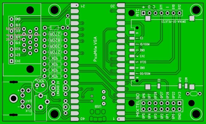 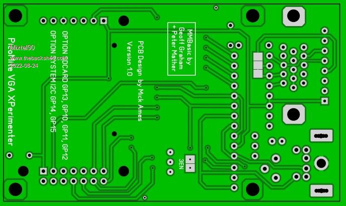 Edited 2022-08-24 05:44 by Mixtel90 Mick Zilog Inside! nascom.info for Nascom & Gemini Preliminary MMBasic docs & my PCB designs |
||||
| Rickard5 Guru Joined: 31/03/2022 Location: United StatesPosts: 463 |
WOW I'm in Love I may be Vulgar, but , while I'm poor, I'm Industrious, Honest, and trustworthy! I Know my Place |
||||
| Volhout Guru Joined: 05/03/2018 Location: NetherlandsPosts: 5994 |
Why is there a non connected via in pin 1 and pin 21 of the pico footprint ? Is that the "pin1" indicator ? PicomiteVGA PETSCII ROBOTS |
||||
| Mixtel90 Guru Joined: 05/10/2019 Location: United KingdomPosts: 8963 |
It's an experiment. I have some 0.4mm dia silver wire here so I've put 0.45mm dia holes through those to pads. I intend to put bits of the wire through the holes (just bent, not soldered) to align the PicoMite on the pads prior to soldering. They are isolated on the bottom. I did the same thing on the 3EN pads so they can be on the bottom of the board but link a track that has to be on the top of the board. In this case the GND connection is a thermal pad on the top (GND is the top of the board only this time). Mick Zilog Inside! nascom.info for Nascom & Gemini Preliminary MMBasic docs & my PCB designs |
||||
| lizby Guru Joined: 17/05/2016 Location: United StatesPosts: 3808 |
I like it. When do we get to see it in "Mixtel90's PCBs"? PicoMite, Armmite F4, SensorKits, MMBasic Hardware, Games, etc. on FOTS |
||||
| Mixtel90 Guru Joined: 05/10/2019 Location: United KingdomPosts: 8963 |
Not far off. I'm a bit busy sorting out stuff for the bathroom at present (various DIY stuff takes time. :( ). I need to sort out a circuit & BOM yet, although they won't take long - I'll be able to crib a lot from the previous boards. :) Mick Zilog Inside! nascom.info for Nascom & Gemini Preliminary MMBasic docs & my PCB designs |
||||
| Rickard5 Guru Joined: 31/03/2022 Location: United StatesPosts: 463 |
 I may be Vulgar, but , while I'm poor, I'm Industrious, Honest, and trustworthy! I Know my Place |
||||
| lizby Guru Joined: 17/05/2016 Location: United StatesPosts: 3808 |
Real world stuff? What a drain on your shed time. PicoMite, Armmite F4, SensorKits, MMBasic Hardware, Games, etc. on FOTS |
||||
| Rickard5 Guru Joined: 31/03/2022 Location: United StatesPosts: 463 |
One day I wondered in to this shed, thinking " Here's a rather fine new time filler", Never Knowing Just the Reading to Keep up would be a full time Job :). I've spent more time Reading here in the last few months than I did in 3 1/2 years at University of Texas  I may be Vulgar, but , while I'm poor, I'm Industrious, Honest, and trustworthy! I Know my Place |
||||
| Mixtel90 Guru Joined: 05/10/2019 Location: United KingdomPosts: 8963 |
It's finally arrived! PicoMite XPerimenter Construction Pack.zip There have been quite a few changes, which I think might be popular. :) Mick Zilog Inside! nascom.info for Nascom & Gemini Preliminary MMBasic docs & my PCB designs |
||||
| lizby Guru Joined: 17/05/2016 Location: United StatesPosts: 3808 |
Ordered, thank you. PicoMite, Armmite F4, SensorKits, MMBasic Hardware, Games, etc. on FOTS |
||||
| Mixtel90 Guru Joined: 05/10/2019 Location: United KingdomPosts: 8963 |
Quick off the mark there. :) Mick Zilog Inside! nascom.info for Nascom & Gemini Preliminary MMBasic docs & my PCB designs |
||||
| lizby Guru Joined: 17/05/2016 Location: United StatesPosts: 3808 |
For $6.38USD, why not? I like the design, and will be looking into a hat for the 2x7 header. PicoMite, Armmite F4, SensorKits, MMBasic Hardware, Games, etc. on FOTS |
||||
| The Back Shed's forum code is written, and hosted, in Australia. | © JAQ Software 2026 |
