
|
|
Forum Index : Microcontroller and PC projects : ArdoMite Power Questions
| Author | Message | ||||
| Rickard5 Guru Joined: 31/03/2022 Location: United StatesPosts: 463 |
I was building ArdoMites today and I couldn't fit the LM1117. I'm guessing the ArdoMite is designed for a SMD part? Mixtel Can you give me the full part Number to source for the ArdoMite Please? Right now I'm powering it off a USB Power Bank! Also one I'm running though the onboard regulator, can I drive 9 volts in ? Thanks I may be Vulgar, but , while I'm poor, I'm Industrious, Honest, and trustworthy! I Know my Place |
||||
| Mixtel90 Guru Joined: 05/10/2019 Location: United KingdomPosts: 8913 |
It's a SOT-223 package SMD part. I'm not sure about an exact part as I don't have your component sources. Farnell are showing no stock, but list LM1117MPX-5.0/NOPB from TI along with several others. Look for LM1117 5V. Mick Zilog Inside! nascom.info for Nascom & Gemini Preliminary MMBasic docs & my PCB designs |
||||
bigmik Guru Joined: 20/06/2011 Location: AustraliaPosts: 2981 |
Hi Rickard, What is an Ardomite? I use 1117 all of the time in SOT223-3 SMD foot print AMS1117 is the same pinout and more or less identical to the LM1117. Make sure you get the correct voltage. Eg, AMS1117-3.3. AMS1117-5 The suffix specifies the voltage. Pinout left to right is GND, OUT (also TAB), Input Regards, Mick Mick's uMite Stuff can be found >>> HERE (Kindly hosted by Dontronics) <<< |
||||
| Mixtel90 Guru Joined: 05/10/2019 Location: United KingdomPosts: 8913 |
@Mick It's a board I did, Mick. PicoMite on an Arduino UNO format PCB. Some of the Arduino hats should fit it and all the pins are in the correct physical place and have, for the most part, similar functions on them. The major difference is that all control pins are 3V3 MAX. Rickard is my Alpha tester. :) @Rickard Power input is exactly the same as an Arduino - the appropriate pins/socket feed the regulator to give 5V, which is output on a pin and fed to the PicoMite for conversion to 3V3. So yes, you can feed the board at 9V but you must use the 3V3 output to feed the supply to switched inputs. Analogue inputs mustn't exceed 3V3. Mick Zilog Inside! nascom.info for Nascom & Gemini Preliminary MMBasic docs & my PCB designs |
||||
| Rickard5 Guru Joined: 31/03/2022 Location: United StatesPosts: 463 |
@ BIG Mik, Mixtel90 Mick though pure Genius, rarely seen independently had the thought of a Picomite to replace the Arduino, and I instantly jumped all over it due to all the Arduino kits I've collected over the years and my lack of C programming ability like the ubiquitous robot 3 wheel cars. My Serious First thought Instantly was to use them in Robot Sumo, and I showed them to my robot friends, and we are working on a PicoMie spec Robot Sumo class that would require one of the 2 ArdoMite controllers and a 3 wheel robot car kit base, basically a class anyone could afford a sub $20- $30 robot and runs off basic so an 11 or 12 year old kid could take the sample code and learn! NO C!!!! The Picture Below is just a Quick Mock up for illustration Rick 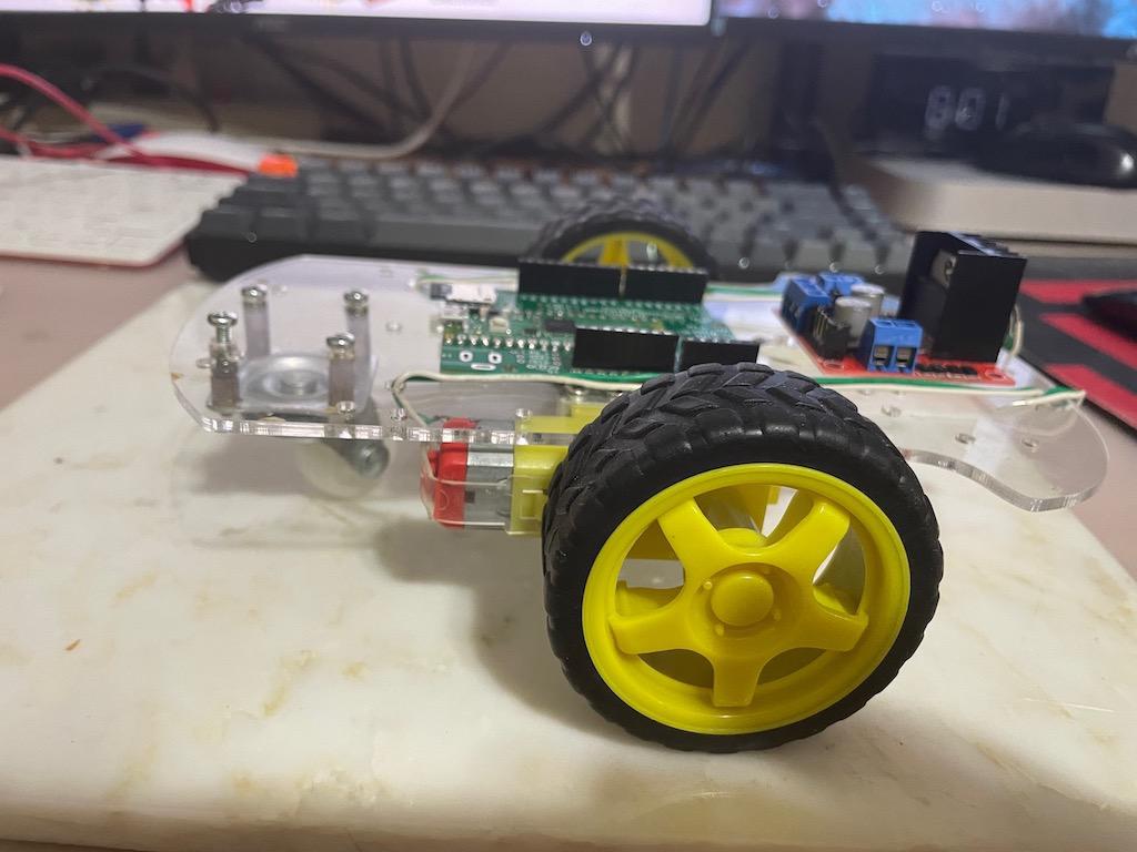 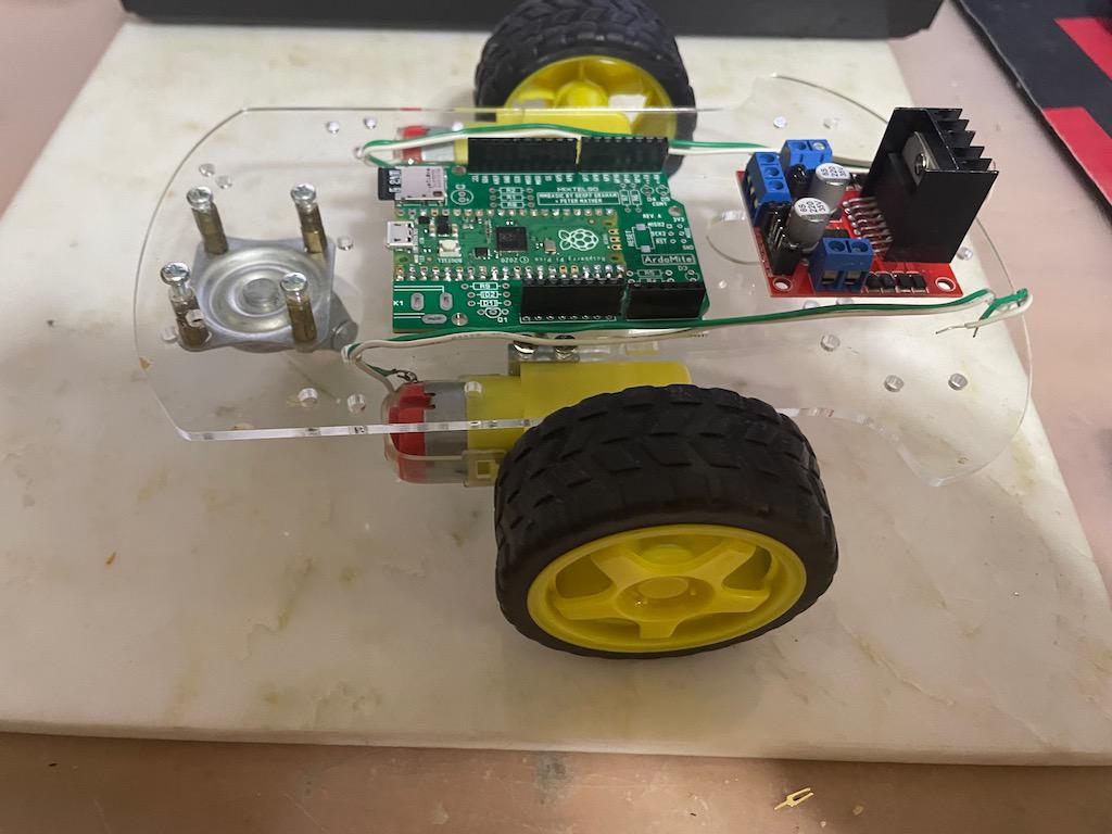 I may be Vulgar, but , while I'm poor, I'm Industrious, Honest, and trustworthy! I Know my Place |
||||
| Mixtel90 Guru Joined: 05/10/2019 Location: United KingdomPosts: 8913 |
That's very nice, Rick. I shall watch this with interest. :) Mick Zilog Inside! nascom.info for Nascom & Gemini Preliminary MMBasic docs & my PCB designs |
||||
| Rickard5 Guru Joined: 31/03/2022 Location: United StatesPosts: 463 |
I'm telling you Mick from the Moment, The Instant I stumbled in here like a Drunk Pikey crashing a Wedding reception, I saw the possibilities for MMBasic and personal Hobby Robotics. The instant out of nowhere a Brit named Mick came up with Physically replacing the Dreaded Arduino with an MMBasic Formfactor Replacement, it was on. now the only thing is how do I easlally send a PWM Signal to a PWM Pin???? it's time to Evangelize these boards and get the masses converted to MMBasic Object Oriented Programming was an evolutionary DEAD END, let it die! bring back 11 or 12 year old kids Typing in programs from compute magazine to learn how to program, so when they are adults they can do real world useful projects, not just "look I just bought XYZ I customized it by setting some Options some one else told me I was allowed to have " I may be Vulgar, but , while I'm poor, I'm Industrious, Honest, and trustworthy! I Know my Place |
||||
| bigmik Guru Joined: 20/06/2011 Location: AustraliaPosts: 2981 |
Hi Rickard, Mick (the other one), Ahh, now I know. I did a google search and couldn't find any reference to it. Re. the Arduino interface. This has been done before and IMHO is of mediocre use, it has been done before but many `hats' are 5V only so are pretty pointless. Plus (again IMHO) the interface was wrong with non standard spacing for no good reason The gap between pins on one side is 0.16" should have made it 0.2" or 0.1" Regards (ducking for cover) Mick (The big one) Mick's uMite Stuff can be found >>> HERE (Kindly hosted by Dontronics) <<< |
||||
| Mixtel90 Guru Joined: 05/10/2019 Location: United KingdomPosts: 8913 |
That's why I have an "S" version, Mick. :) The same size but physically incompatible because everything, including fixing holes (IIRC), is on the same 0.1" matrix. I dislike the Arduino hardware and hate the IDE. :) The vanilla ArdoMite is of some use because it (usually) fits into the same enclosures and on the same mounting hardware as an Arduino. It was also far easier to do than getting a PicoMite into a Raspberry Pi format. :) The manual for it makes it very clear that it isn't an Arduino and that standard hats may not work. It's interesting though, because correctly designed hats should usually work on this (if the user writes supporting software) because they are supposed to use the IOREF pin to power all inputs and set the output voltages even if they are powered from 5V. In this case IOREF is at 3V3 rather than 5V, that's all. Mick Zilog Inside! nascom.info for Nascom & Gemini Preliminary MMBasic docs & my PCB designs |
||||
| The Back Shed's forum code is written, and hosted, in Australia. | © JAQ Software 2026 |
