
|
|
Forum Index : Microcontroller and PC projects : PicoMite "pantry" AM transmitter
| Author | Message | ||||
| matherp Guru Joined: 11/12/2012 Location: United KingdomPosts: 11548 |
My wife says this is a complete waste of time but it kept me amused for a day To make this work you need one of these AD9833 modules. It must be this version which has a variable gain output stage. 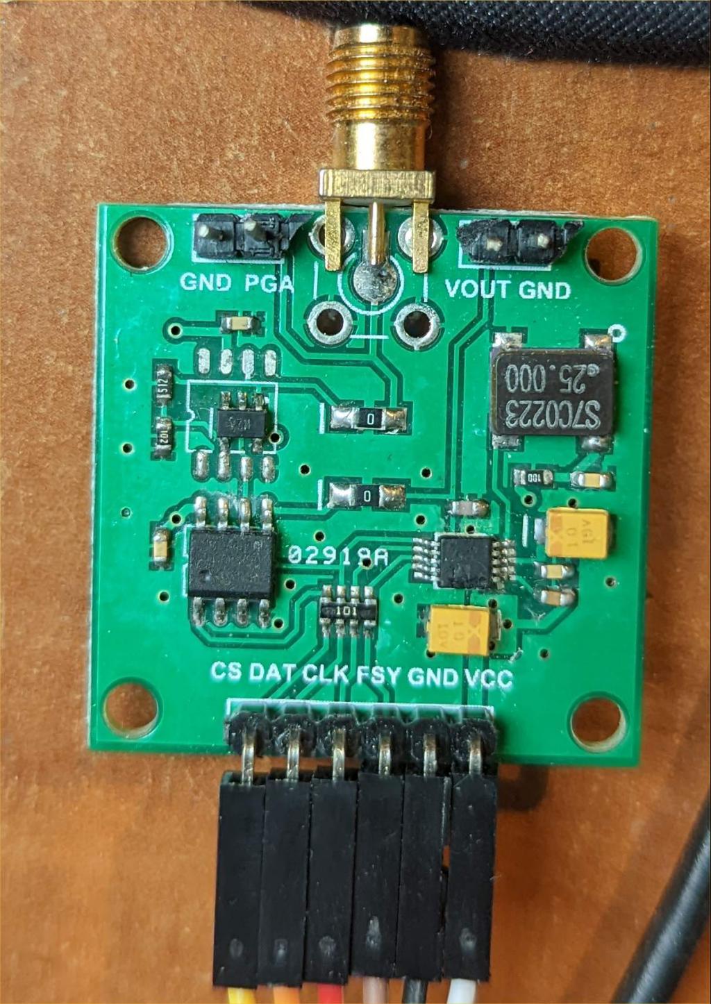 The PicoMite firmware needed a slight tweak to expose some new functions to the CSUB. The updated PicoMiteVGA version is attached. I'll include the changes in a proper release later. PicoMiteVGA.zip The Basic code is very simple. It sets the signal generator to a fixed frequency sine wave (891KHz is unused in the UK) by bitbanging the SPI bus. It then calls the Cfunction which replaces the normal PWM output from the audio interrupt routine with itself. This means that each interrupt (normally 44.1KHz) the CSUB function "audio" is called and it changes the amplitude of the sinewave carrier to create the AM signal. There are two modes of operation. If the optional analogue input pin is specified in the call to the CSUB then the pin is sampled each interrupt and the amplitude adjusted accordingly. If the analogue pin is omitted in the call to the CSUB then whatever is output using the play command will be used to modify the amplitude (WAV files, TONES, SOUNDS). Notes: the PicoMite must be set to run at 378MHz for this to work (OPTION CPUSPEED 378000). The AD9833 module should be powered with 5V not 3.3V. Because the ARM M0 core does not include an integer divide the compiler calls a function to do this. This means you can't use the / symbol in a CSUB unless it optimises to a shift (/2 etc.). I have added a callable routine IDiv to the firmware to get round this. The output of the AD9833 is of course single ended so the waveform looks a bit odd but the radio picks it up fine with a short wire connected to the PGA pin. This is a 50 ohm output and I'm sure the "analogue" experts can suggest a suitable circuit to improve this. 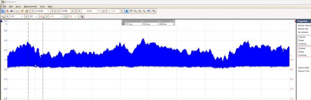 Option explicit Option default integer ' pin allocations Dim Freq =891000, Level = 128 Dim track$ Const CS = 1 � � � � �' pin for MCP41010 chip select (CS) pin on module Const DAT= 2 � � � � �' pin for SPI Data Const CLKP = 4 � � � �' pin for SPI Clk Const FSY = 5 � � � � ' pin for AD9833 chip select(FSY) pin on module Const ANA = 34 � � � �' pin for analogue sampling if required Const EXTERNAL=1 � � �' external analogue sampling enabled setpins setfreq setlevel if EXTERNAL then �AUDIO CS,CLKP,DAT,ANA �Play tone 400,400 'trigger the audio interrupt �Play pause 'interrupt keeps running during pauses �Pause 100 �do �loop else �AUDIO CS,CLKP,DAT �play wav "" �track$=MM.Info(track) �If track$<>"OFF" Then Print track$ �Do � �If MM.Info(track)<>track$ Then � � �track$=MM.Info(track) � � �If track$="OFF" Then end � � �Print track$ � �EndIf � �Loop endif ' Sub setpins �Pin(CS) = 1 �SetPin CS, dout �Pin(FSY) = 1 �SetPin FSY, dout �Pin(DAT) = 0 �SetPin DAT, dout �Pin(CLKP) = 1 �SetPin CLKP, dout �SetPin ANA,ain End Sub Sub SetFreq �Local f, c, f1, f2 �Const oscillator = 25000000 � 'Crystal frequency �Const p = &B1100000000000000 �Const B28 = &H2000 �Const RESET = &H100 �f = (Freq * (1 << 28)) \ oscillator �f1 = (f And &H3FFF) Or &H4000 �f2 = (f >> 14) Or &H4000 �Pin(FSY) = 0 �s16 c Or RESET Or B28 �s16 f1 �s16 f2 �s16 p �s16 c �Pin(FSY) = 1 End Sub ' sets the digital potentiometer (0-255) ' note that when running on 3.3V the maximum undistorted level is 211 Sub SetLevel �Pin(CS) = 0 �s16 level Or &H1100 �Pin(CS) = 1 End Sub Sub s16 a% Local i%, j% For i% = 15 To 0 Step -1 �j%=1<<i% �If a% And j% Then � �Pin(DAT)=1 �Else � �Pin(DAT)=0 �EndIf �Pin(CLKP)=0 �Pause 1 �Pin(CLKP)=1 �Pause 1 Next End Sub CSub AUDIO 'CSpin, CLKpin, DATpin [,ANApin] 0000002C 'audio 46C6B5F0 00044E25 000D6833 4B246818 681B2105 4798B500 68D86833 D1382800 19644B20 01E0681B 4B1F8819 4798681B 26802388 4303015B 4698B29B 4D172710 02364C17 682BE014 68982106 47986823 2105682B 68236858 46C04798 2106682B 68236858 46C04798 08763F01 D0082F00 421E4643 682BD1E7 68982105 47986823 682BE7E6 68182106 47986823 46B8BC80 4B06BDF0 4798681B E7C91100 1000038C 10000328 100003DC 100003D8 10000324 'main 46C6B5F0 B084B500 A8010006 0003001D 46904C16 000F447C C306CC06 801A8822 D0042E00 D0022F00 2B004643 4B10D102 4798681B 68314B0F 6011681A 6839681A 46416051 6809681A 681B6091 D00A2D00 60DA682A 4A094B08 447A681B B004601A 46B8BC80 60DDBDF0 46C0E7F4 00000068 10000368 1000038C 100003D4 FFFFFEF3 206E6950 6F727245 00000072 End CSub CSUB #include "PicoCFunctions.h" #include <stdint.h> #define CSpin CFuncRam[0] #define CLKpin CFuncRam[1] #define DATpin CFuncRam[2] #define ANApin CFuncRam[3] static void audio(uint16_t left, uint16_t right){ uint16_t v; PinSetBit(CSpin,LATCLR); if(ANApin==0)v=(IDiv(((int)left+(int)right)*128L,AUDIO_WRAP)) | 0x1100; else v=(uint16_t)(ExtInp(ANApin)>>4) | (uint16_t)0x1100; for(uint16_t i=32768;i>=1;i>>=1){ if(v & i)PinSetBit(DATpin,LATSET); else PinSetBit(DATpin,LATCLR); PinSetBit(CLKpin,LATCLR); NOP(); PinSetBit(CLKpin,LATSET); NOP(); } PinSetBit(CSpin,LATSET); } void main(long long int *CS, long long int *CLK, long long int *DAT, long long int *ANA ){ �const char pe[]="Pin Error"; �if(CS==0 || CLK==0 || DAT==0)error((char *)pe); �CSpin=*CS; �CLKpin=*CLK; �DATpin=*DAT; �if(ANA!=0)ANApin=*ANA; �else ANApin=0; �AudioOutputVector=(unsigned int)&audio; //Set up the address for the audio interrupt output routine } Updated version of PicoCFunctions.h PicoCFunctions.zip Edited 2022-11-16 03:16 by matherp |
||||
| gadgetjack Senior Member Joined: 15/07/2016 Location: United StatesPosts: 233 |
You never cease to amaze me with your projects. Thank you for sharing. |
||||
| Pluto Guru Joined: 09/06/2017 Location: FinlandPosts: 411 |
Peter, I build the project as you described with exactly the same AD9833 module as you have. The module outputs the carrier wave exactly at the correct frequency. I have a signal generator (a la Geoff) connected to the analog input pin 34 (ADC2). The problem is that I am not able to get any modulation on the carrier wave.  > option list PicoMiteVGA MMBasic Version 5.07.05RC9 OPTION FLASH SIZE 4194304 OPTION KEYBOARD US OPTION CPUSPEED (KHz) 378000 Are there any more option that I should install? I do not have a SD card connected as I intended to test with just analog input. Tested also with ADC0 and ADC1. No difference. No modulation. Fred |
||||
| matherp Guru Joined: 11/12/2012 Location: United KingdomPosts: 11548 |
Try just connecting pin 34 to 3.3V and then to GND you should see the modulation changing. If not check pin 34 is working as a simple analogue input. UPDATE Just noticed you haven't got OPTION AUDIO set. This is needed to create the interrupts. You can also test by replacing PLAY WAV "" with for example PLAY TONE 400,400 Edited 2022-11-17 01:12 by matherp |
||||
| Tinine Guru Joined: 30/03/2016 Location: United KingdomPosts: 1646 |
Pete, I find that header-parting to be downright offensive  Not exactly cheap but I use this and the end-result is near darned perfect Craig |
||||
| Pluto Guru Joined: 09/06/2017 Location: FinlandPosts: 411 |
Thanks Peter!  Added OPTION AUDIO GP26,GP27 and a SD-card with a wav-file. I thought that OPTION AUDIO was only required for audio output. Works now and I have just started my own broadcasting company. Hmm... it is closer to Narrowcasting. Just and just hearable inside the house. Works now also with analog input. 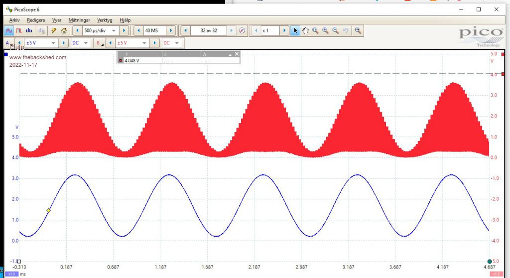 This became a very nice toy to play with! Stay tuned on 891kHz...maybe you can hear my 1000Hz signal.  Thanks Fred |
||||
| The Back Shed's forum code is written, and hosted, in Australia. | © JAQ Software 2026 |
