
|
|
Forum Index : Microcontroller and PC projects : PicoMite LC meter
| Author | Message | ||||
| Pluto Guru Joined: 09/06/2017 Location: FinlandPosts: 411 |
I have just completed a small project. It is a inductance and capacitance meter based on a PicoMite. It seems to work quite well: -Capacitors down to a few pF and up to a few hundred nF. A normal multimeter can anyhow handle the higher values. -Inductors down to below 1uH and up to at least 6mH (highest in the L box). 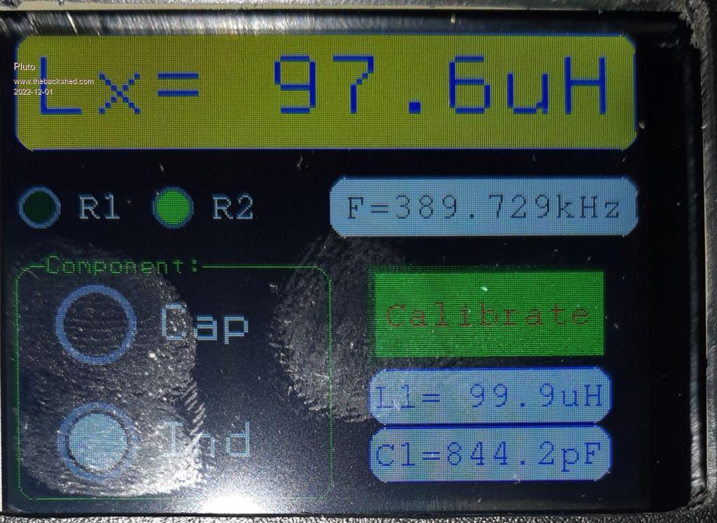 Quick and dirty build on a prototyping board. The comparator had to be put on an adapter (SOT-23 size). 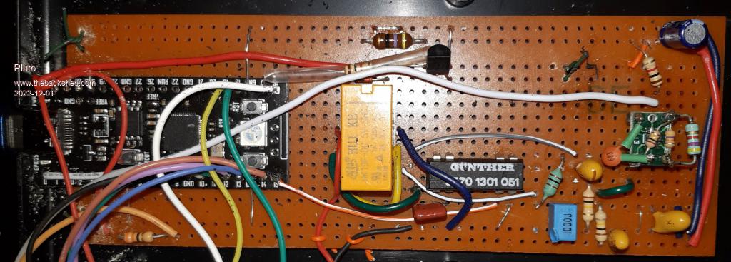 option list PicoMite MMBasic Version 5.07.05RC8 OPTION SYSTEM SPI GP18,GP19,GP16 OPTION AUTORUN 3 OPTION FLASH SIZE 4194304 OPTION CPUSPEED (KHz) 126000 OPTION LCDPANEL ILI9341, LANDSCAPE,GP10,GP14,GP13 OPTION GUI CONTROLS 12 OPTION TOUCH GP12,GP11 GUI CALIBRATE 0, 3958, 266, -896, 662 > 'LCmeter FN3.bas Fredrik Nissfolk 30.11.2022 'GP0measure frequency/period using PIO. PIO-program by Volhout. 'Circuit source: SiliconChip January 2018 p.45. 'Modifications from SC article: '-Arduino Uno changed to PicoMite 5.0705 @126MHz. '-LCD 240x320 2.4" ILII9341 '-Comparator changed from LM311 to LMV331 in order to have 3.3V operation. '-47k feedback replaced by 47k parallel with 4.7k (by experimentation) '-Comparator output pull-up 4.7k reduced to 1k. '-Comparator output series resistor 6.8k to microcontroller skipped. '-Supply to comparator-circuit now 3.3V from PicoMite. Rely2 powerd from USB 5V. CLS Const C2=810 'Calibration capacitor. Const RLY_5V=22 'GP17 RELY2 Cx/Lx controlled by BC337 Const RLY_REED=20 'GP15 RELY1 connects calibration capacitor. DIM Lx,Cx as float 'Measured L and C DIM F1L,L1L,F2L,C1L,F1C,F2C,C1C,L1C as Float 'Calibration values DIM avg,avg1,Frekvens,Counts As Float 'used for calculation of average Freq and Counts Var restore SetPin RLY_5V,dout SetPin RLY_REED,dout Pin(RLY_5V)=0 ' pin RLY_5V=0 sets meter in capacitance measurement mode. Pin(RLY_REED)=0 ' pinRLY_REED=0 disconnects the calibration capacitor C2. CONST h=mm.hres,v=mm.vres font 1,2 GUI RADIO #1,"Cap",h/8,v*5/8,20 CTRLVAL(#1)=1 GUI RADIO #2,"Ind",h/8,v*7/8,20 font 1,1 GUI FRAME #3,"Component:",0,v/2,h/2,v/2,rgb(green) font 4,3 GUI DISPLAYBOX #4,0,0,h,v*2/8,rgb(blue),rgb(yellow) CTRLVAL(#4)="LC meter" font 2,1 GUI BUTTON #5,"Calibrate",9*h/16,8*v/16,125,50,rgb(red),RGB(green) CTRLVAL(#5)=0 GUI DISPLAYBOX #6,h/2,v*5/16,h/2,1/8*v,rgb(black),rgb(White) CTRLVAL(#6)="Frequency" GUI LED #7,"R1",12,v*6/16,10,rgb(green) GUI LED #8,"R2",h/4,v*6/16,10,RGB(green) CTRLVAL(#7)=0:CTRLVAL(#8)=0 GUI DISPLAYBOX #9,9*h/16,23/32*v,125,28,RGB(blue),rgb(white) CTRLVAL(#9)="L1" GUI DISPLAYBOX #10,9*h/16,27/32*v,125,28,RGB(blue),rgb(white) CTRLVAL(#10)="C1" 'RelyTest 'Just to see (and hear) that 5V rely is working. ' '--------------------------------------------- 'Volhout's PIO program: 'pio program measure pause and pulse time from GP0 in us and push both to FIFO '0 E020 'set X=0 '1 A029 'X -> fffffff '2 00C4 'jmp (pin=1) to loop2 '3 0042 'count loop1 '4 0045 'count loop2 '5 00C4 'jmp (pin=1) in loop2 '6 A0C9 'mov -X to ISR '7 8000 'push noblock '8 0000 'jmp 0 (rest is filled with 0 = jmp->0) Dim a%(7)=(&h004200C4A029E020,&h8000A0C900C40045,0,0,0,0,0,0) 'f=63e6 '2MHz gives 1us per count resolution f=126e6 'configure pio1 e0=Pio(execctrl 0,0,&h1f) 'use gp0 for PIN p=0 'no GPxx pins for PIO 'program pio1 and start PIO program 1,a%() PIO init machine 1,0,f,p,e0,,0 'start pio 1,0 from adress 0 PIO start 1,0 Dim cnt%(4) '------End of Volhout's PIO program------------------------- 'LxCalibration 'before any measurements are done. With connected test probes. 'CxCalibration 'before any measurements are done. With open test probes. 'Program will remind you later to calibrate. '--Main program loop---------- Do IF CtrlVal(#1)=1 then MeasureCx:CTRLVAL(#9)="L1="+str$(L1C,3,1)+"uH":CTRLVAL(#10)="C1="+str$(C1C,3,1)+"pF" IF CtrlVal(#2)=1 THEN MeasureLx:CTRLVAL(#9)="L1="+str$(L1L,3,1)+"uH":CTRLVAL(#10)="C1="+str$(C1L,3,1)+"pF" IF CTRLVAL(#1)=1 and CTRLVAL(#5)=1 then CxCalibration IF CTRLVAL(#2)=1 and CTRLVAL(#5)=1 then LxCalibration CTRLVAL(#8)=Pin(RLY_5V):CTRLVAL(#7)=Pin(RLY_REED) IF CtrlVal(#2)=1 and C1L=0 THEN CTRLVAL(#4)="No calib!" IF CtrlVal(#1)=1 and C1C=0 THEN CTRLVAL(#4)="No calib!" Loop 'While Inkey$="" PIO stop 1,0 End '--------------------------- Sub RelyTest For i =1 To 1000 Pin(RLY_5V)=1 Pause 10 Pin(RLY_5V)=0 Pause 10 Next i End Sub Sub LxCalibration 'Set 5V rely for Lx input and calibrate with closed test clips. font 1,2 CTRLVAL(#4)="CALIBRATION" pause 1000 do r=MsgBOX("SHORT INPUT!","OK") loop until r=1 CTRLVAL(#4)="..WAIT.." Print "!!!!!!!!!!!!!!!!!!!!!!!!!!!!" Print "Calibration starting" Print "SHORTCUT THE TEST PROBES" Print "---------------------------" Pin(RLY_5V)=1:Pin(RLY_REED)=0:CTRLVAL(#8)=Pin(RLY_5V):CTRLVAL(#7)=Pin(RLY_REED) Pause 2000 MeasureFrequency(20000) F1L=Frekvens:Print "Calibration F1L=";F1L;"Hz";" Counts=";Counts 'Add C2 by closing REED-rely Pin(RLY_REED)=1:CTRLVAL(#8)=Pin(RLY_5V):CTRLVAL(#7)=Pin(RLY_REED) Pause 1000 MeasureFrequency(20000) F2L=Frekvens:Print "Calibration F2L=";F2L;"Hz";" Counts=";Counts C1L=C2*F2L*F2L/((F1L*F1L)-(F2L*F2L)):Print "Calibration C1L=";C1L;"pF":Print " C2=";C2;"pF calibr cap" L1L=1/(4*Pi*Pi*F1L*F1L*C1L*1e-12)*1e6:Print "Calibration L1L=";L1L;"uH" Pin(RLY_REED)=0 'Disconnect the calibration capacitor C2 CTRLVAL(#8)=Pin(RLY_5V):CTRLVAL(#7)=Pin(RLY_REED) CTRLVAL(#5)=0 var save F1L,C1L,L1L Pause 500 End Sub Sub CxCalibration 'Set rely2 for Cx input and calibrate with open test clips. font 1,2 CTRLVAL(#4)="CALIBRATION" pause 1000 do r=MsgBOX("OPEN INPUT!","OK") loop until r=1 CTRLVAL(#4)="..WAIT.." Print "!!!!!!!!!!!!!!!!!!!!!!!!!!!!" Print "CX Calibration starting" Print "OPEN THE TEST PROBES" Print "---------------------------" Pin(RLY_5V)=0:Pin(RLY_REED)=0:CTRLVAL(#8)=Pin(RLY_5V):CTRLVAL(#7)=Pin(RLY_REED) Pause 2000 MeasureFrequency(20000) F1C=Frekvens:Print "Calibration F1=";F1C;"Hz";" Counts=";Counts 'Add C2 by closing REED-rely Pin(RLY_REED)=1:CTRLVAL(#8)=Pin(RLY_5V):CTRLVAL(#7)=Pin(RLY_REED) Pause 1000 MeasureFrequency(20000) F2C=Frekvens:Print "Calibration F2C=";F2C;"Hz";" Counts=";Counts C1C=C2*F2C*F2C/((F1C*F1C)-(F2C*F2C)):Print "Calibration C1C=";C1C;"pF":Print " C2=";C2;"pF calibr cap" L1C=1/(4*Pi*Pi*F1C*F1C*C1C*1e-12)*1e6:Print "Calibration L1C=";L1C;"uH" Pin(RLY_REED)=0 'Disconnect the calibration capacitor C2 CTRLVAL(#8)=Pin(RLY_5V):CTRLVAL(#7)=Pin(RLY_REED) CTRLVAL(#5)=0 VAR save F1C,C1C,L1C Pause 500 End Sub Sub MeasureFrequency(nbr As integer) 'Rely-settings according to what is given by the caller of this sub. 'nbr: number of measurements for average avg=0 avg1=0 PIO start 1,0 For i=1 To nbr PIO read 1,0,5,cnt%() 'read fifo pio 1 seq 0 period1% = cnt%(4)+3 'correction for push and loop freq=f/(2*period1%) 'calc freq avg=avg+freq avg1=avg1+cnt%(4) Next i PIO stop 1,0 Frekvens=avg/nbr Counts=avg1/nbr CTRLVAL(#6)="F="+str$(Frekvens/1000,3,3)+"kHz" End Sub Sub MeasureLx Pin(RLY_REED)=0 'Calibration Capacitor C2 always disconnected. Pin(RLY_5V)=1 'Set in Lx-measurement mode. CTRLVAL(#8)=Pin(RLY_5V):CTRLVAL(#7)=Pin(RLY_REED) Pause 500 'debouncing MeasureFrequency(2000) Lx=L1L*(F1L*F1L/(Frekvens*Frekvens)-1) CTRLVAL(#4)="Lx=" If Lx<-0.5 Then CTRLVAL(#4)="Lx=ERROR" 'if Lx>=0 and Lx <1 then print "Lx=";str$(Lx*1000,3,0);"nH" if Lx>=-0.50 and Lx <1 then CTRLVAL(#4)="Lx="+str$(Lx*1000,3,0)+"nH" 'If Lx>=1 And Lx<1000 Then Print "Lx=";Str$(Lx,3,1);"uH" If Lx>=1 And Lx<1000 Then CTRLVAL(#4)="Lx="+Str$(Lx,3,1)+"uH" 'If Lx>=1000 And Lx<1000000 Then Print "Lx=";Str$(Lx/1000,3,1);"mH" If Lx>=1000 And Lx<1000000 Then CTRLVAL(#4)="Lx="+Str$(Lx/1000,3,1)+"mH" 'If Lx>=1000000 Then Print "Lx ERROR" If Lx>=1000000 Then CTRLVAL(#4)="Lx ERROR" End Sub Sub MeasureCx Pin(RLY_REED)=0 'Calibration Capacitor C2 always disconnected. Pin(RLY_5V)=0 'Set in Cx-measurement mode. CTRLVAL(#8)=Pin(RLY_5V):CTRLVAL(#7)=Pin(RLY_REED) Pause 500 'debouncing MeasureFrequency(2000) Cx=C1C*(F1C*F1C/(Frekvens*Frekvens)-1) CTRLVAL(#4)="Cx=" If Cx<-0.5 Then CTRLVAL(#4)="Cx ERROR" 'If Cx>=0 And Cx<1000 Then Print "Cx="+Str$(Cx,3,1)+"pF" If Cx>=-0.50 And Cx<1000 Then CTRLVAL(#4)="Cx="+Str$(Cx,3,1)+"pF" 'If Cx>=1000 And Cx<1000000 Then Print "Cx="+Str$(Cx/1000,3,1)+"nF" If Cx>=1000 And Cx<1000000 Then CTRLVAL(#4)="Cx="+Str$(Cx/1000,3,1)+"nF" 'If Cx>=1000000 And Cx<1000000000 Then Print "Cx="+Str$(Cx/1e6,3,1)+"uF" If Cx>=1000000 And Cx<1000000000 Then CTRLVAL(#4)="Cx="+Str$(Cx/1e6,3,1)+"uF" 'If Cx>=1e9 Then Print "Cx ERROR" If Cx>=1e9 Then CTRLVAL(#4)="Cx ERROR" End Sub The frequency measurements are done by the PIO-program, that Volhout presented some time ago. My project started from some testing that I did with his code. When I saw how well his code worked, I had to find something to use it for! As the maximum frequency used by the meter is about 550kHz, I assume that his code is a bit overkill for this meter. Probably the standard frequency metering would have been sufficient? |
||||
| Volhout Guru Joined: 05/03/2018 Location: NetherlandsPosts: 5953 |
Hi Pluto, Nice project !!! Can you shart a circuit diagram ? Volhout PicomiteVGA PETSCII ROBOTS |
||||
| Pluto Guru Joined: 09/06/2017 Location: FinlandPosts: 411 |
I will make a drawing soon... |
||||
| Pluto Guru Joined: 09/06/2017 Location: FinlandPosts: 411 |
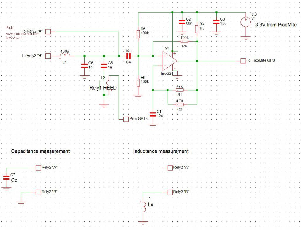 The front-end (selection of either L or C measurement) was too difficult to draw with the SIMetrix software, so I had to draw that by hand. Depending on the relay configuration you have to carefully check before you start wireing. I didn't and I spent a long time trying to figure out why not working. On my particular rely the common pin was not between the NC and NO pins! 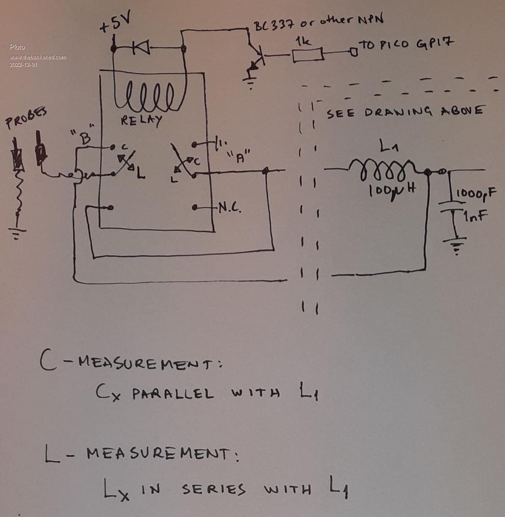 |
||||
| Volhout Guru Joined: 05/03/2018 Location: NetherlandsPosts: 5953 |
Hi Pluto, Nice, you are building an oscillator (LC) around an opamp (LMV331) and and parallel/serial place inductors and capacitors under test. Very basic, smart. You can of coarse extend the range by having an additional relay replace the 100uH with 10mH. Maybe have to adapt C1 and C4. Thanks for sharing.... Volhout PicomiteVGA PETSCII ROBOTS |
||||
| Pluto Guru Joined: 09/06/2017 Location: FinlandPosts: 411 |
LMV331 is actually a comparator. Compared to other capacitance/inductance meters that I have bought/built, this one gives more reliable results for the very lowest L and C values. I decided to have separate calibration routines for L and C. There is a small difference due to the different signal routings when the 5V relay is on or off. Once the calibration is done for each L and C the values are saved and ready at start up of the meter. Recalibration might be required when measuring L below 5uH or C below 5pF as there is some small drift (~100nH) when the meater is "warming" up. The origin of the meter: https://pe2bz.philpem.me.uk/Comm01/-%20TestEquip/-%20Tester-NonActiveDevice/Cl-251-IndCap-MeterKit/lc-meter-project.htm#circuit-osc You are right Volhout, it would be quite easy to extend the range, but for the moment being it is enough for my purpose. |
||||
| The Back Shed's forum code is written, and hosted, in Australia. | © JAQ Software 2026 |
