
|
|
Forum Index : Microcontroller and PC projects : Cute little 2.1 amp for your PC...
| Author | Message | ||||
| hitsware2 Guru Joined: 03/08/2019 Location: United StatesPosts: 719 |
Yes . The problem being that , perceptually , the degradation is cumulative . But then if one does not hear , or even listen for it , ..... Who cares ? Edited 2023-01-15 05:01 by hitsware2 my site |
||||
plover Guru Joined: 18/04/2013 Location: AustraliaPosts: 306 |
In the years just before covid arrived on the scene I was playing around with some of these class D amps for driving LEDs with various frequencies. I did not set out to do this but an instrument I bought, to me became suspicious, so I had to trouble shoot and it turned out the amp had a problem. This started me looking at replacement options. The supplier provided a new amp but I continued to make improvements to my way of thinking. One interesting thought I had, running different loads on the left and right channel, say sound in one and LEDs in the other. This brought me to look at the outputs, are they actually isolated/floating? with respect to DC ground? I never found answers I was happy with. At the time I remember testing with a couple of back to front power LEDs with a common series resistor to limit current because depending on volume the voltage could go to around 60V. I only managed to test one channel before the plandemic hit, that was basically the end of my electronics as I switched to medical study big time. Well I did not blow the LEDs and I did not work out if the outputs are 'isolated'. Is there any easy answers? |
||||
| phil99 Guru Joined: 11/02/2018 Location: AustraliaPosts: 2620 |
If the manufacturer does not clearly state that the outputs are isolated then it's almost certain they aren't. It is possible it has no mains earth connection and is isolated in that sense, but are unlikely to be isolated from the signal ground. The outputs are usually bridge type with single supply rail so the no-signal voltage on them is about half supply voltage, to signal ground. |
||||
| plover Guru Joined: 18/04/2013 Location: AustraliaPosts: 306 |
phil99 Thanks for posting, my memory isd poor but your post seems to have triggered something in my mind. Seems my earlier conclusion just before packing away the electronics for that project I has come to think likewise, I noted the H bridge. I think that was why I added two LEDs parallel back to front. I also think I can remember they both lit up when signal was increased. If I can find a rainy day I may have a quick peek when I get my workshop partly cleaned up so I can actually fit in there and use more than just a multi meter.  |
||||
| Mixtel90 Guru Joined: 05/10/2019 Location: United KingdomPosts: 7877 |
I got the amp that's intended to drive a reversed mains transformer for my turntable speed control yesterday. 43mm x 30mm x 8mm. And 30W mono. In actual fact I won't be aiming for that and it's unlikely to ever provide more than 5W, but it cost the same as a lower powered one. :) This is a bridged class D (intended for car audio systems really) as I don't need ground referenced outputs. Just waiting for the transformer to turn up now and I can start to play. :) Sheesh... I remember my dad having a 25W mono PA amp. It had a pair of 6L6 in push-pull into an output transformer that I kept for many years after the amp was scrapped! Mick Zilog Inside! nascom.info for Nascom & Gemini Preliminary MMBasic docs & my PCB designs |
||||
Grogster Admin Group Joined: 31/12/2012 Location: New ZealandPosts: 9593 |
My new amp has arrived, and it is just as cute as the first one, but it IS just a smidgen bigger to allow for the output LC filters. 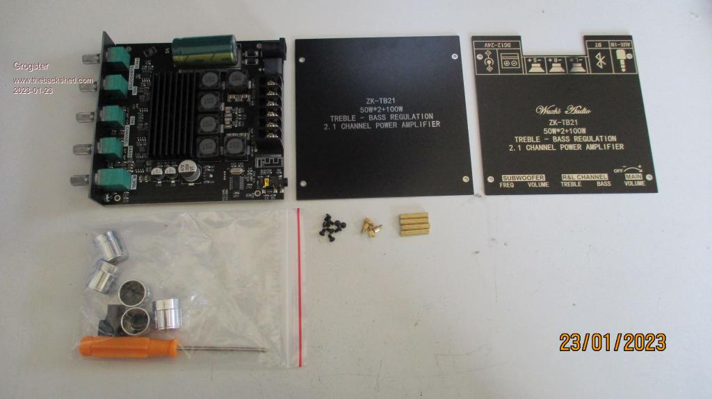 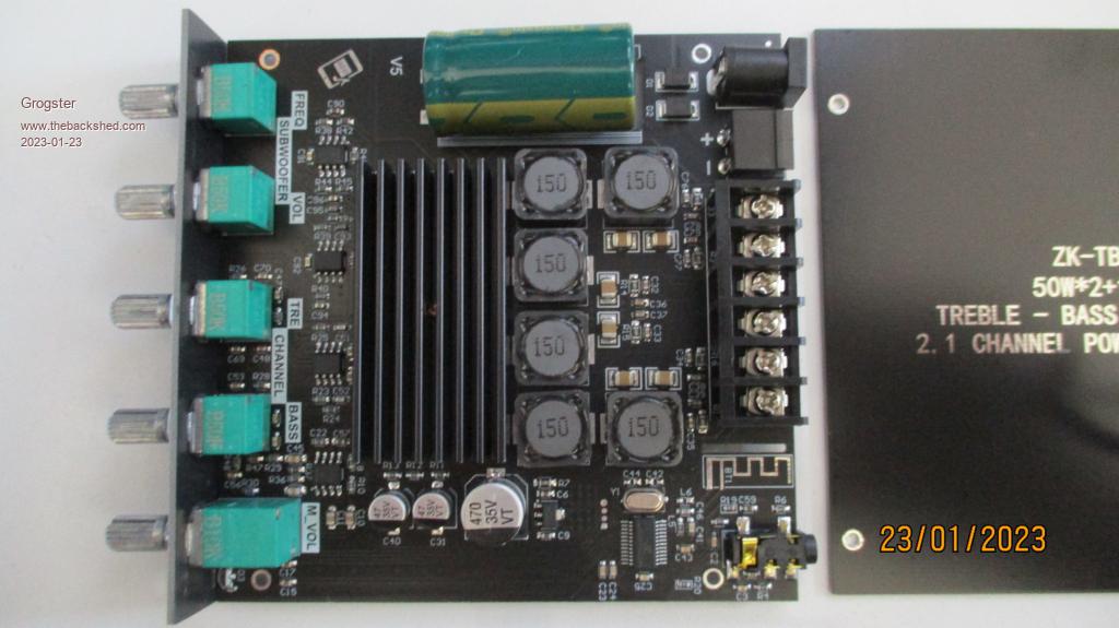 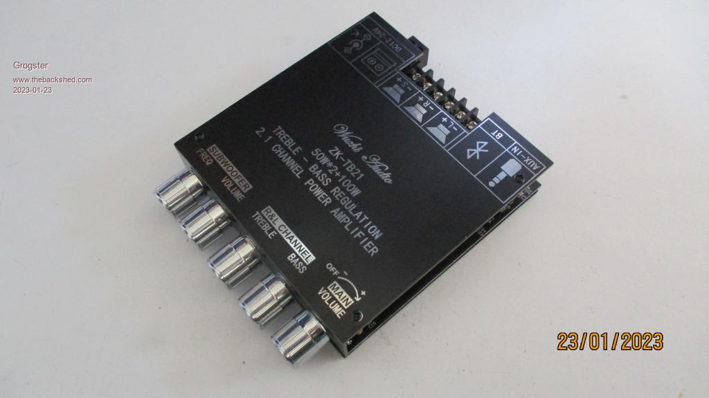 Have not hooked it up just yet, but the old one without the filters has been performing beautifully since I put it on-line. It might be radiating a bit though, so it will be a good idea to replace it. I plan to do that tomorrow. Smoke makes things work. When the smoke gets out, it stops! |
||||
| Mixtel90 Guru Joined: 05/10/2019 Location: United KingdomPosts: 7877 |
That version looks every bit as nice. :) Mick Zilog Inside! nascom.info for Nascom & Gemini Preliminary MMBasic docs & my PCB designs |
||||
| Grogster Admin Group Joined: 31/12/2012 Location: New ZealandPosts: 9593 |
Yes, I plan to give it a bit of a push tomorrow night with various music styles to see how it sounds. If anything like the unfiltered version, I am expecting the same kind of sound. Smoke makes things work. When the smoke gets out, it stops! |
||||
| Mixtel90 Guru Joined: 05/10/2019 Location: United KingdomPosts: 7877 |
The top might get rounded a bit as it flies round those coils before making it's dizzy way out, but that's all. :) Mick Zilog Inside! nascom.info for Nascom & Gemini Preliminary MMBasic docs & my PCB designs |
||||
| The Back Shed's forum code is written, and hosted, in Australia. | © JAQ Software 2025 |
