
|
|
Forum Index : Microcontroller and PC projects : PicX - Pico Experimenter
| Author | Message | ||||
| Mixtel90 Guru Joined: 05/10/2019 Location: United KingdomPosts: 8913 |
Born out of frustration. :) Of course, it's 100mm x 100mm. 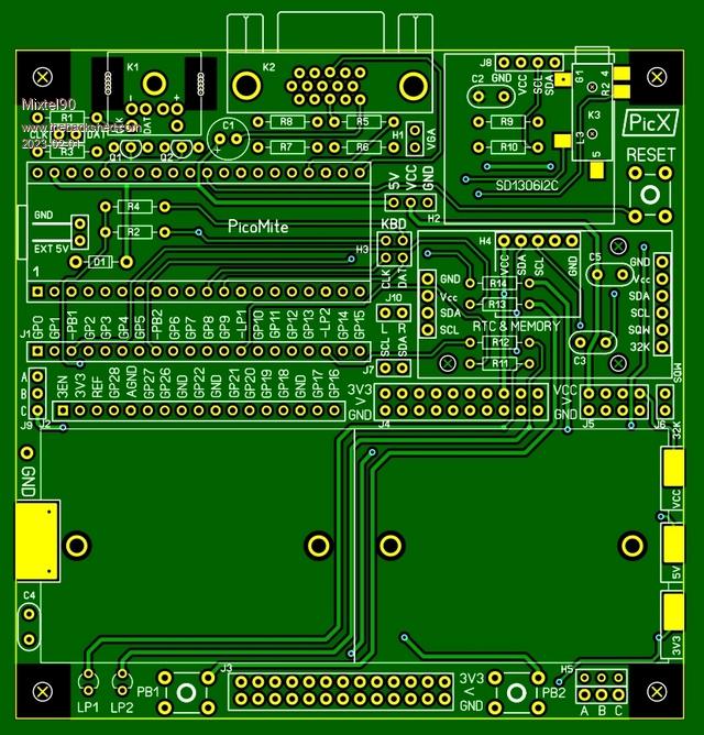 PicX.zip Edited 2023-02-01 07:38 by Mixtel90 Mick Zilog Inside! nascom.info for Nascom & Gemini Preliminary MMBasic docs & my PCB designs |
||||
| Solar Mike Guru Joined: 08/02/2015 Location: New ZealandPosts: 1217 |
Cool, I might have a go at building one. Note in order for the 3.3v switch mode chip to be disabled and its output substituted by an analog PSU, by taking its 3.3_EN input low, it has to have power on the VSYS input pin, so the chip is active and can respond to the low on the 3.3_EN line. Cheers Mike |
||||
| Mixtel90 Guru Joined: 05/10/2019 Location: United KingdomPosts: 8913 |
It normally would have as the 5V supply would be via the USB input. VSYS is fed from VBUS via an on-board diode. The Ext 5V input does the same thing. It's not visible in that pic as I switched off the bottom copper layer to make it prettier. :) Edit: I'll find out if it works or not in a couple of weeks - I've ordered some. :) Edited 2023-02-01 19:40 by Mixtel90 Mick Zilog Inside! nascom.info for Nascom & Gemini Preliminary MMBasic docs & my PCB designs |
||||
| Mixtel90 Guru Joined: 05/10/2019 Location: United KingdomPosts: 8913 |
JLCPCB came up with the goods this morning, so a new toy to play with soon. :) Dry assembly has been ok so far, which is a good thing. I have some bits (including the breadboards) on order. The jack socket is going to have to wait until I can make up a sensible order from RS. 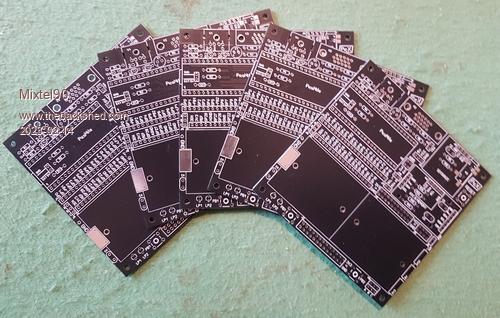 Edited 2023-02-14 22:30 by Mixtel90 Mick Zilog Inside! nascom.info for Nascom & Gemini Preliminary MMBasic docs & my PCB designs |
||||
| Mixtel90 Guru Joined: 05/10/2019 Location: United KingdomPosts: 8913 |
Laydees an' Gennelmen! We have a prototype for your delectation! Please excuse the flux grunge - I've no flux remover and isopropyl alcohol makes the board sticky. 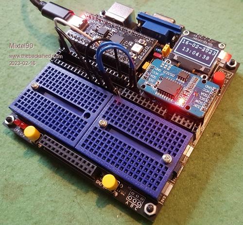 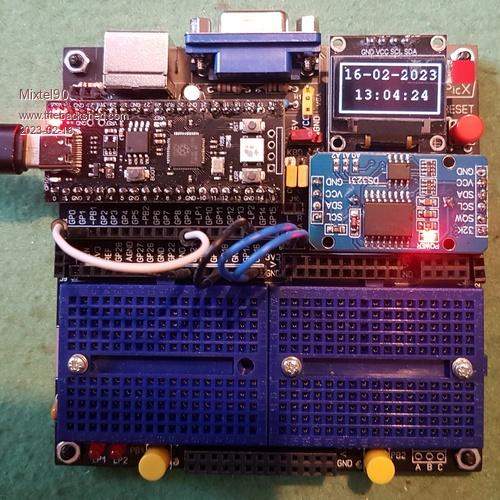 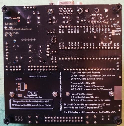 If you need more breadboard area you can expand it at the right-hand end, just directly outwards or with more breadboards above and/or below the first one. This is also a pretty good illustration of why you should avoid black or blue breadboards - the holes are harder to see. :) Incidentally, the two blue Dupont leads are connecting the I2C bus to the PicoMite (a YD-RP2040). Not tested with VGA and PS/2 yet. Mick Zilog Inside! nascom.info for Nascom & Gemini Preliminary MMBasic docs & my PCB designs |
||||
| al18 Senior Member Joined: 06/07/2019 Location: United StatesPosts: 241 |
Looks like another great board to play with - thanks. What Pico board is in the pictures? How is it different from a Raspberry Pi Pico? |
||||
Grogster Admin Group Joined: 31/12/2012 Location: New ZealandPosts: 9977 |
Very nice work, Mick.   Smoke makes things work. When the smoke gets out, it stops! |
||||
| Mixtel90 Guru Joined: 05/10/2019 Location: United KingdomPosts: 8913 |
The Pico alternative is the YD-RP2040 from Ali Express. Very briefly: USB-C connector 16MB flash WS2812 LED on GP23 (if you close a link). GP23 is also on a pin. Reset button User button (GP24) Power LED ADC_VREF has moved, not on a main pin now. Replaced by ADC3 Linear voltage regulator. Means that minimum input voltage is higher (3.46V). No 3V3_EN now. It's not as fast as an official Pico, in that you can't overclock it as much. Apart from that it seems to be ok. The power arrangements are a bit different - you can't take 5V from pin 39 as it's a VIN with a diode now. (For this board it's a good idea to short out pins 39 and 40 on the module itself.) I'm in the process of updating the "manual" for it, in light of the things I've come across while building the prototype. I've not found any board errors so far. I'm just playing with version 2. So far it has a position to fasten a spacer under the LCD display to give it a bit of support. It also has a SMD microSD socket connected to GP0, GP1, GP2 & GP3. I've hard-wired that as I've not found anywhere to put a connector! Doesn't matter, as if there's no card plugged in the GPs are available. EDIT: I've just been looking at the voltage regulator on the YD-RP2040. Part number ME6125C33. The data sheet is a bit sparse! I was interested to note that although it's stated current rating is 300mA it's absolute maximum power handling is only 250mW. This is quite a limitation. If the incoming supply is 5v then the absolute maximum current is 0.25/(5-3.3) = 147mA. The board itself will probably require around 45mA so the user will almost certainly get less than 100mA to play with before the regulator starts to shut down (at least I hope it shuts down rather than burns out - the output current hasn't been exceeded, this is excess power dissipation and the data sheet is mute on that). It might be a good idea, if using this board for LCD displays, to run any backlights from 5V to keep the load off the regulator. Also be careful if powering a USB keyboard at 3V3. Edited 2023-02-17 20:14 by Mixtel90 Mick Zilog Inside! nascom.info for Nascom & Gemini Preliminary MMBasic docs & my PCB designs |
||||
| Pluto Guru Joined: 09/06/2017 Location: FinlandPosts: 411 |
ME6215C33 datasheet claims both overcurrent shutdown and shortcircuit current shutdown. I have used these for quite some time and I have not had any issues. Have been OK up to 378MHz. Have not tested for max current capacity. +USB-C +16MB flash on order (since last year! Not here yet!) +cheaper than the "standard" green modules. /Pluto |
||||
| Mixtel90 Guru Joined: 05/10/2019 Location: United KingdomPosts: 8913 |
That regulator does give me a little concern. You can easily exceed maximum power dissipation without triggering short circuit or overcurrent protection. 250mA is well within continuous current ratings but will dissipate 425mW. We don't know if there is enough copper area anyway (doubtful). The data sheet says nothing about current limiting or shutting down on high temperature (although most regs seem to do). Given the maximum IO current of the RP2040 there shouldn't be too much of a problem for most people. At least the linear reg is quiet. :) EDIT: If using the latest version of the PicoMite VGA firmware it's likely that the YD-RP2040 won't work at 252MHz. The one I tried won't. I think the flash chip might be too slow on these. If you do try it the device will probably lock up and you'll have to clear the flash then reload the firmware to rescue it. Edited 2023-02-18 06:01 by Mixtel90 Mick Zilog Inside! nascom.info for Nascom & Gemini Preliminary MMBasic docs & my PCB designs |
||||
| JohnS Guru Joined: 18/11/2011 Location: United KingdomPosts: 4336 |
So I don't really know whether it's reasonably possible (& affordable), but could some circuitry be added to improve robustness? Opto-isolators, maybe? Resettable fuses? Buffers? Hopefully you get the idea. I'm thinking that experimenters (cf prototypers) may short things / use inappropriate voltages and so on. I suppose anything semi-expected to blow should be socketed. Geoff has mentioned how robust the PIC32 is, but the Pico isn't, if I've understood correctly. John Edited 2023-02-18 20:14 by JohnS |
||||
| JohnS Guru Joined: 18/11/2011 Location: United KingdomPosts: 4336 |
Separately, maybe an ADC as standard, if cheap, to cover up for the Pico's bug? John |
||||
| Mixtel90 Guru Joined: 05/10/2019 Location: United KingdomPosts: 8913 |
Not on this one, John. I did a board aimed at educational use not long ago (PicoMite XPerimenter). That takes "hats" that are intended for isolators, resistor/diode networks etc. exactly for this purpose. It can also be built as either a VGA or a non-VGA "Control" type, and can also be a backpack for an ILI9341 display. You can get two out f a 100x100 PCB. The "hats" can be made from any 0.1" matrix board if you don't want to sort out PCBs. Details & construction pack in my sig. PicX is intended for those who need raw access to the pins. Adding isolation, ADCs etc would only get in the way (and I've run out of PCB area anyway. lol). The idea is to have a basic system of Pico, usable breadboard area and RTC (to keep times & dates on development files) all in one place to make things easy. Everything essential except for the PS/2 level shifting mosfets will unplug. (I tried socketing the mosfets but there isn't enough space). The Pico should be treated as CMOS logic. It has low drive capability. It may not be incredibly robust, but it's cheap - much cheaper than the PIC32 range. :) Having said that, they do seem to be able to take a moderate amount of abuse. Mick Zilog Inside! nascom.info for Nascom & Gemini Preliminary MMBasic docs & my PCB designs |
||||
| JohnS Guru Joined: 18/11/2011 Location: United KingdomPosts: 4336 |
OK... maybe a new name, "Pico Prototyper". BTW Is it good to get 2 out of 100x100? Small isn't always better. John |
||||
| Mixtel90 Guru Joined: 05/10/2019 Location: United KingdomPosts: 8913 |
The size was because of the market. Yes, you can get more on if you use more board space, but if that extra stuff isn't required (because it is intended to be added as "hats") then there's no point in having it. Better to let the customer get two boards for the price of one. More kids in a class can have them then. That design had a very specific target. The "hats" can be bolted on. The Pico isn't removable. The Pico can be pre-programmed with course work, for example, so the kids can't change it. It doesn't *have* to be used in that way, of course. You could easily fit opto-couplers and an ADC chip onto a hat and use it as a general purpose PicoMite VGA board. Another specific target was the little PLC that I designed. It's for use on 24VDC systems and can switch mains voltages via relays. Rugged enough for many people, although perhaps not the ultimate. I've no intention of producing a fully isolated, bomb proof system. (Although you can get close to one using my MPC design with opto-isolation etc.). First, they don't exist. Someone *will* find a way to destroy it eventually. Secondly, it costs more for a couple of relays and one quad opto-isolator than it does for a PicoMite. You have to stop somewhere. :) These things can be done, but they are better done for particular applications. Mick Zilog Inside! nascom.info for Nascom & Gemini Preliminary MMBasic docs & my PCB designs |
||||
| Mixtel90 Guru Joined: 05/10/2019 Location: United KingdomPosts: 8913 |
@JohnS For an ADC converter can I suggest one of the ADS1115 modules that are around? 3V3 supply, 4-inputs, 16-bit and I2C connection. This one looks like a good option. Mick Zilog Inside! nascom.info for Nascom & Gemini Preliminary MMBasic docs & my PCB designs |
||||
| JohnS Guru Joined: 18/11/2011 Location: United KingdomPosts: 4336 |
Thanks. John |
||||
| The Back Shed's forum code is written, and hosted, in Australia. | © JAQ Software 2026 |
