
|
|
Forum Index : Microcontroller and PC projects : OLED 1.3" SSD1306
| Author | Message | ||||
| asknik2022 Regular Member Joined: 26/03/2022 Location: United KingdomPosts: 94 |
I have a OLED SSD1306 1.3" I2C which works perfectly using gp0,gp1 I have a OLED SSD1306 1.3" SPI/I2C which I have soldered modified to I2C as per instructions on back of display I have connected as follows GND >> GND VCC >> VCC SCL >> CLK SDA >> MOSI But I get nothing. Do I need to connect RES,DC,CS, and if so where to. Edited 2023-03-22 01:33 by asknik2022 |
||||
| Pluto Guru Joined: 09/06/2017 Location: FinlandPosts: 411 |
Yes you have to connect all. See the p.44 in PicoMite User Manual MMBasic Ver 5.07.06 (if you are using PicoMite). |
||||
| asknik2022 Regular Member Joined: 26/03/2022 Location: United KingdomPosts: 94 |
This is all it says on page 44 about I2C SSD1306 OPTION LCDPANEL SSD1306I2C, OR [,offset] Initialises a OLED display using the SSD1306 controller with an I2C interface. This supports 128 * 64 resolution. An additional parameter offset may be specified to control the position of the display. 0.96" displays typically need a value of 0. 1.3" displays typically need a value of 2. Default if omitted is 0. I have converted the display from SPI to I2C so shouldn't I be using OPTION LCDPANEL SSD1306I2C,L,2 |
||||
| Pluto Guru Joined: 09/06/2017 Location: FinlandPosts: 411 |
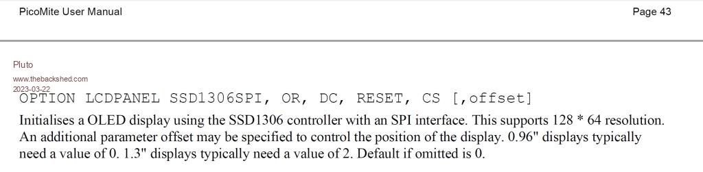 |
||||
| Pluto Guru Joined: 09/06/2017 Location: FinlandPosts: 411 |
Check: https://geoffg.net/picomite.html for the latest manual. |
||||
| Mixtel90 Guru Joined: 05/10/2019 Location: United KingdomPosts: 8913 |
If it's been converted from SPI to I2C then I can't see why the SPI information is relevant. As far as I can see the connections are correct. VCC goes to 3V3. None of the other pins are used by I2C, but connect RES to 3V3 and the other two pins to GND. Did you remember to short out R8? Are there any pullups on SDA and SCL? It may be worth trying 10k for these. Info from https://www.instructables.com/OLED-Tutorial-Convert-SPI-to-I2C/ Mick Zilog Inside! nascom.info for Nascom & Gemini Preliminary MMBasic docs & my PCB designs |
||||
| Pluto Guru Joined: 09/06/2017 Location: FinlandPosts: 411 |
Sorry for the confusion  I understood that you had it working with I2C and wanted to change to SPI. |
||||
| asknik2022 Regular Member Joined: 26/03/2022 Location: United KingdomPosts: 94 |
I managed to get this working by using an ESP8266 and prgrammed it via Arduino IDE However I had to connect RES to the reset pin in order to get it to work. I would prefer to use the pi pico but there is no reset pin. On the Pi Pico connecting the RES to VCC(5v or 3.3V) all I get is full screen of dots. ?? Edited 2023-03-31 02:36 by asknik2022 |
||||
| asknik2022 Regular Member Joined: 26/03/2022 Location: United KingdomPosts: 94 |
Can anybody help me on this please I managed to get this working by using an ESP8266 and prgrammed it via Arduino IDE However I had to connect RES to the reset pin in order to get it to work. I would prefer to use the pi pico but there is no reset pin. On the Pi Pico connecting the RES to VCC(5v or 3.3V) all I get is full screen of dots. |
||||
| matherp Guru Joined: 11/12/2012 Location: United KingdomPosts: 11547 |
Have you tried with the latest beta? |
||||
| asknik2022 Regular Member Joined: 26/03/2022 Location: United KingdomPosts: 94 |
YEP |
||||
| phil99 Guru Joined: 11/02/2018 Location: AustraliaPosts: 3294 |
"I would prefer to use the pi pico but there is no reset pin." The RUN pin is a "Not Reset" pin. Pull it low and the Pico resets. PS. A 100nF from RUN to Gnd. can prevent unintended resets. |
||||
| mozzie Guru Joined: 15/06/2020 Location: AustraliaPosts: 390 |
@asknik2022 Some of those OLED have a jumper to select I2C address on the back, to select from &h78 and &h7A (0x78 / 0x7A) All the units here are set to &h78 and work with MMbasic so might be worth checking on the unit you have there. Another suggestion is to try an R/C network on the reset of the OLED, try 10k to +V and 2.2uf to ground, with SPI the reset is driven but using I2C it's not from MMBasic. Regards, Lyle. Edited 2023-03-31 12:10 by mozzie |
||||
| Mixtel90 Guru Joined: 05/10/2019 Location: United KingdomPosts: 8913 |
Or just put reset to any pin and pulse it before accessing. Mick Zilog Inside! nascom.info for Nascom & Gemini Preliminary MMBasic docs & my PCB designs |
||||
| The Back Shed's forum code is written, and hosted, in Australia. | © JAQ Software 2026 |
