
|
|
Forum Index : Microcontroller and PC projects : MicroMiteVga project
| Page 1 of 2 |
|||||
| Author | Message | ||||
| IanRogers Senior Member Joined: 09/12/2022 Location: United KingdomPosts: 152 |
Hello all Just putting my first system together. Just a couple 'O' questions. @Mick I have a 5v RTC module unit, will it do, ie. do the SDA / SCL pins on the pico need protection? Normally I2C pins are good.. I'm using an MCP4822 for sound, Is the output able to drive a lil speaker or do I need a buffer.. As you can guess. I am more digital than analogue so before the magic smoke, I thought I'd seek help. The RTC module is one of those "Tiny RTC I2C Modules" https://www.cricklewoodelectronics.com/images/D/RTC1b.jpg Cheers I'd give my left arm to be ambidextrous |
||||
| lizby Guru Joined: 17/05/2016 Location: United StatesPosts: 3788 |
I'd say just try the RTC at 3V3--it'll probably work. But the DS1307 is noted for being a pretty poor time keeper. Better is DS3231. PicoMite, Armmite F4, SensorKits, MMBasic Hardware, Games, etc. on FOTS |
||||
| phil99 Guru Joined: 11/02/2018 Location: AustraliaPosts: 3294 |
Replaced the crystal in a DS1307 with one salvaged from a dead motherboard. Keeps excellent time now. |
||||
| Mixtel90 Guru Joined: 05/10/2019 Location: United KingdomPosts: 8913 |
I've not used that particular RTC module. It's a 4V5-5V5 device and shouldn't run on 3V3. There are on-board pull-up resistors (4K7) to 5V. Ideally you should use level shifters with this module but you might get away with it providing your 5V rail isn't something like 5V5. You could play safe an power the VCC line through a schottky diode to lose a tiny bit of voltage. https://lastminuteengineers.com/ds1307-rtc-arduino-tutorial/ The MCP4822 is SPI, write only (there is no MISO). The output is at 2V peak and benefits a lot from a simple RC network. You have plenty of output level but not enough to drive a speaker directly. Headphones via a resistor might be ok as the output stage is relatively meaty. Mick Zilog Inside! nascom.info for Nascom & Gemini Preliminary MMBasic docs & my PCB designs |
||||
| IanRogers Senior Member Joined: 09/12/2022 Location: United KingdomPosts: 152 |
I have a 'lil' level shifter I used for keypad and there are two free slots, I'll use them. The audio is only tidley speakers, If I put a 8 way dip socket on the PCB I can just try resistors to suit. Thanks for the reply BTW.. its only for playing with, so I don't care too much about time keeping. Edited 2023-05-25 02:06 by IanRogers I'd give my left arm to be ambidextrous |
||||
| Mixtel90 Guru Joined: 05/10/2019 Location: United KingdomPosts: 8913 |
Peter used 120R and 100nF for the filter on his VGA 1.1 board. That would be a good starting point, depending on your load. Mick Zilog Inside! nascom.info for Nascom & Gemini Preliminary MMBasic docs & my PCB designs |
||||
| Volhout Guru Joined: 05/03/2018 Location: NetherlandsPosts: 5945 |
I use the same RTC module. You must power it from 5v (Vsys of pico). The module has 4.7k pullup resistors. If you add 10k pull down resistors on your breadboard you get nice 3.3 v logic levels. Rtc chip works fine with 3.3v levels. For me it is working fine. Volhout Remark: my unit needed a rechargeable battery, if you use a lithium or alkaline battery you may destroy the battery since it will try to charge i Edited 2023-05-25 03:38 by Volhout PicomiteVGA PETSCII ROBOTS |
||||
| IanRogers Senior Member Joined: 09/12/2022 Location: United KingdomPosts: 152 |
That makes sense.. There is a BATT pin available Normally you feed a rechargable battery via a small diode with a current limiting resistor.. If I leave that disconnected I can use a standard CR2032. Let you know how that goes. I'd give my left arm to be ambidextrous |
||||
| IanRogers Senior Member Joined: 09/12/2022 Location: United KingdomPosts: 152 |
LOL just realized I have the title wrong... LOL PicoMiteVGA. too long in the tooth to care though.. You all know what I mean. I'd give my left arm to be ambidextrous |
||||
| Mixtel90 Guru Joined: 05/10/2019 Location: United KingdomPosts: 8913 |
I suspected as much. :) Mick Zilog Inside! nascom.info for Nascom & Gemini Preliminary MMBasic docs & my PCB designs |
||||
| IanRogers Senior Member Joined: 09/12/2022 Location: United KingdomPosts: 152 |
@Lizby. The audio will be as above the MCP4822! I bought a couple to play with I'm contemplating using a couple of those PAm8302A amps Should give a good sound.. I'll feed the amps via trimmer so I can get a decent level The whole thing is on a stripboard ( nothing fancy ) but it's coming along quite well I don't seem to have a trimmer suitable for the "GREEN" colour balance but I'll sort it somehow. I'd give my left arm to be ambidextrous |
||||
| IanRogers Senior Member Joined: 09/12/2022 Location: United KingdomPosts: 152 |
OH! Yes! I wonder if admin can change my title as it is VERY off. I'd give my left arm to be ambidextrous |
||||
| Mixtel90 Guru Joined: 05/10/2019 Location: United KingdomPosts: 8913 |
Why not use the 4-resistor VGA circuit? It's a lot easier and you don't need a trimmer. :) Mick Zilog Inside! nascom.info for Nascom & Gemini Preliminary MMBasic docs & my PCB designs |
||||
| lizby Guru Joined: 17/05/2016 Location: United StatesPosts: 3788 |
Ok, here's the schematic pinched from Peter's EasyEDA project: 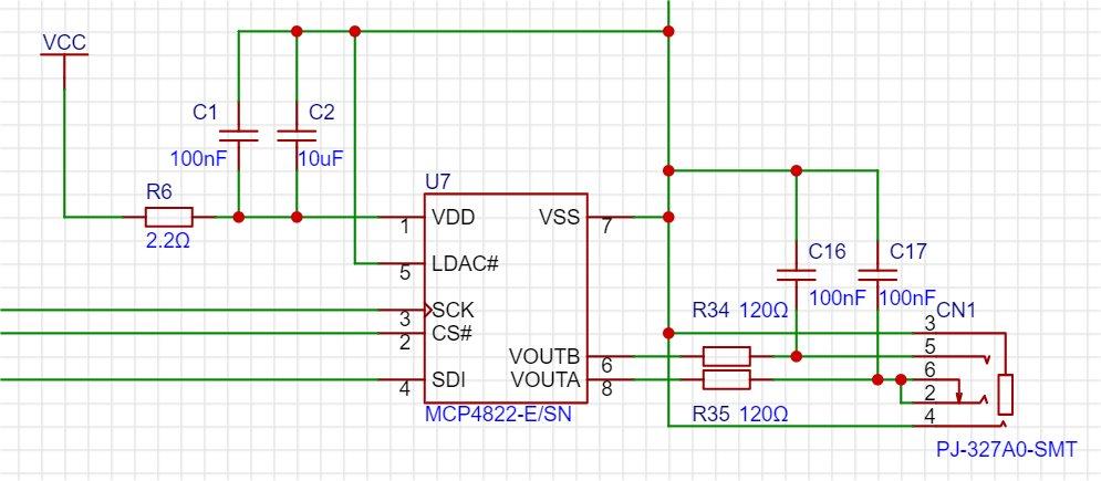 If it's the only SPI device, then /CS could be tied low, so only 4 pins need to be wired: V+, V-, SCK, MOSI/SDI (but maybe the firmware needs for CS to be specified). ~ Edited 2023-06-09 23:20 by lizby PicoMite, Armmite F4, SensorKits, MMBasic Hardware, Games, etc. on FOTS |
||||
| Mixtel90 Guru Joined: 05/10/2019 Location: United KingdomPosts: 8913 |
I think you may need CS# as part of the SPI synchronising process. Not sure. Consider yourself lucky that you don't need LDAC# too. :) Mick Zilog Inside! nascom.info for Nascom & Gemini Preliminary MMBasic docs & my PCB designs |
||||
| matherp Guru Joined: 11/12/2012 Location: United KingdomPosts: 11546 |
Without CS it won't work |
||||
| lizby Guru Joined: 17/05/2016 Location: United StatesPosts: 3788 |
Thanks. Second thought had made me believe that would be the case. Here's the inductor circuit from the EasyEDA V1.0 file: 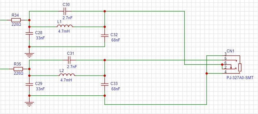 I don't have and can't find on aliexpress through-hole 2.7nF capacitors. Will either 2.2nF or 3.3nF suit? PicoMite, Armmite F4, SensorKits, MMBasic Hardware, Games, etc. on FOTS |
||||
| Mixtel90 Guru Joined: 05/10/2019 Location: United KingdomPosts: 8913 |
You'll get something, but it won't be as accurate as it should be as it's a tuned circuit. A 1nf and a 1.5nF in parallel would be closer. Mick Zilog Inside! nascom.info for Nascom & Gemini Preliminary MMBasic docs & my PCB designs |
||||
| lizby Guru Joined: 17/05/2016 Location: United StatesPosts: 3788 |
Ok, I found these 2700pF PicoMite, Armmite F4, SensorKits, MMBasic Hardware, Games, etc. on FOTS |
||||
| IanRogers Senior Member Joined: 09/12/2022 Location: United KingdomPosts: 152 |
Which is that one... All the cicuits I have seen requires a green trim to get the white as best as possible? Can you show me the one you are talking about all the circuits from Geoff's site have the 8 resistors? I'd give my left arm to be ambidextrous |
||||
| Page 1 of 2 |
|||||
| The Back Shed's forum code is written, and hosted, in Australia. | © JAQ Software 2026 |
