
|
|
Forum Index : Microcontroller and PC projects : Getting the best out of Pico ADC
| Author | Message | ||||
| Volhout Guru Joined: 05/03/2018 Location: NetherlandsPosts: 5058 |
Assume you have an array A!() that is size X (1024) Your display area is S (320) Then you create (DIM) an array T!() that is size X-S (in this case 1024-320=704) DIM T!(X-S) You copy the first X-S values from array A!() into T!() You do a dummy=MATH(MIN T!(),trigger) trigger will be a pointer that is between 0 and X-S in array T!() Use the same trigger as a pointer in array A!() and you will always have sufficient display points for your window. copying part of an array into another can be done using MEMORY COPY FLOAT 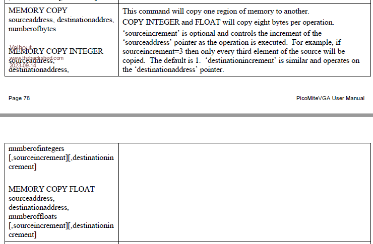 The memory address you get from PEEK(VARADDR )  So the code for that would be (untested !! currently no pico at hand) MEMORY COPY FLOAT PEEK(VARADDR A!()), PEEK(VARADDR T!()), X-S This would be a relatively fast way of doing it... Volhout Edited 2023-09-14 17:21 by Volhout PicomiteVGA PETSCII ROBOTS |
||||
| stanleyella Guru Joined: 25/06/2022 Location: United KingdomPosts: 2540 |
|
||||
| phil99 Guru Joined: 11/02/2018 Location: AustraliaPosts: 2611 |
Look at the bottom of the previous page. What Volhout described above is tested and working in my scope program. It can be adapted to yours quite easily. |
||||
| carlschneider Senior Member Joined: 04/08/2023 Location: South AfricaPosts: 158 |
Hi there I have been browsing with interest and wonder if any consideration has been given to DSO capabilities? This link may be the seed... Cheers Carl Retirement is tough on Hobbies without a day job |
||||
| phil99 Guru Joined: 11/02/2018 Location: AustraliaPosts: 2611 |
All the scope programs in this thread are rudimentary DSOs. Make the buffer arrays much bigger and add a means to scan back and forth and you have a proper DSO. @Stan, Here is the last scope program you posted with the trigger replaced with the Memory Copy version. it now gives a nice stable display. Dim integer indx%,x% Edit.Dim float samples!(640), samples2(320) '320 = 640-screen width samp1.addr = Peek(VARADDR samples!()) 'find the memory address of the start of the in/out array samp2.addr = Peek(VARADDR samples2()) 'find the memory address of the start of the temp array SetPin (31), AIn 'this is adc input pin ADC open 50000,1 'this is sampling rate FRAMEBUFFER CREATE F:FRAMEBUFFER LAYER L:FRAMEBUFFER WRITE L 'all graphics to layer L Line 159,0,159,239,,RGB(blue) Line 0,119,319,119,,RGB(blue) 'draw cross to layer L FRAMEBUFFER WRITE F 'all graphics to framebuffer Do ADC start samples!() 'get new samples Math scale samples!(),199/3.3,samples!():Math add samples!(),20,samples!() 'trigger ' c%=0 ' Do :If samples!(c%+1) > 0.1 Then If samples!(c%) < 0.2 Then Exit ' Inc c%:Loop While c%<240 'trigger Memory copy FLOAT samp1.addr, samp2.addr, 321 'copy to shorter temp array low! = Math(Min samples2(),indx%) ':Print low!,indx% 'find the index of the minimum Memory copy FLOAT samp1.addr + indx% * 8, samp1.addr, 321 'copy back to intput array, starting at indx% FRAMEBUFFER COPY L,F 'copy cross on layer L to framebuffer For x%=1 To 320 'screen width Line x%,240-samples!(x%),x%,240-samples!(x%-1),,RGB(red) 'draw new sample from sample(c%) Pixel x%,240-samples!(x%),RGB(white) 'plot new sample from sample(c%) Next x% FRAMEBUFFER COPY F,N 'copy frame buffer to display Loop To eliminate the output array the temp array is copied back to the input array. Edited 2023-09-16 15:39 by phil99 |
||||
| Mixtel90 Guru Joined: 05/10/2019 Location: United KingdomPosts: 7865 |
Sort of. :) It can look like a 'scope and behave somewhat like a 'scope (especially if you add an analogue front end to give Y shift and gain switching switching) but it's very rudimentary performance-wise. Even the infamous DSO130 kit from ebay has better frequency performance, I think. This is definitely a fun project, but with an absolute max 500 ksps with one trace or 250 lsps with two it's not going to set records, even as an audio 'scope. Mick Zilog Inside! nascom.info for Nascom & Gemini Preliminary MMBasic docs & my PCB designs |
||||
| stanleyella Guru Joined: 25/06/2022 Location: United KingdomPosts: 2540 |
|
||||
| NPHighview Senior Member Joined: 02/09/2020 Location: United StatesPosts: 202 |
In case you'd like to use the Waveshare Pico-LCD-1.3 display carrier, I've just received a couple, and have figured out how to use the OPTIONs to set the SYSTEM SPI and LCDPANEL configuration. I'm going to try using this board as a scope display, since it already has four pushbuttons (and an x-y joystick on it!) PicoMite MMBasic Version 5.07.07 OPTION SYSTEM SPI GP10,GP11,GP28 OPTION LCDPANEL ST7789, LANDSCAPE,GP8,GP12,GP9,GP13 There is no SD card socket, so reading data is not an option, and MISO pin isn't present. Only CLOCK (GP10) and MOSI (GP11) are specifiable. There is no MISO pin, but setting MISOpin tp GP28 (otherwise unused) works (so far). The carrier uses an ST7789VW controller (at 240x240 full color), which I've used in the past on one of their larger carrier boards *with* an SD card socket. Their documentation is at this link. The board schematic is at this link. 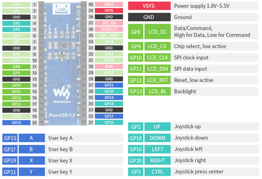 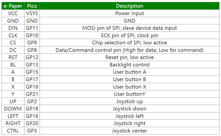 Edited 2023-09-18 03:44 by NPHighview Live in the Future. It's Just Starting Now! |
||||
| matherp Guru Joined: 11/12/2012 Location: United KingdomPosts: 10240 |
You need to use something like Option system spi gp10,gp11,gp28 option lcdpanel st7789,l,gp8,gp12,gp9,gp13 |
||||
| thwill Guru Joined: 16/09/2019 Location: United KingdomPosts: 4302 |
I'm not entirely sure which pins you need free for this rudimentary DSO, but it looks to me like the Game*Mite might be a suitable device (bigger display and chunkier controls than the Pico-LCD-1.3) if you want to build a portable one but don't (yet) want to make a custom PCB. Best wishes, Tom MMBasic for Linux, Game*Mite, CMM2 Welcome Tape, Creaky old text adventures |
||||
| NPHighview Senior Member Joined: 02/09/2020 Location: United StatesPosts: 202 |
Thanks, Peter & Tom - Peter - through brute force process of elimination, I was able to figure out the SPI settings, but I really appreciate your monitoring the forum! Tom - I need GP18 (pin 24 or other), GP26/27 (pins 31 and 32) accessible via some sort of connectors. While this board has a larger :-) display than the 0.96, and has buttons and joystick, it doesn't bring out those leads. I'm about to try soldering "pin and cup" style through-connectors to see if I can't somehow accommodate both. I'll contact you via messaging to find out how I might be able to get my hands on a Game*Mite. With Peter's suggested configuration, this display does work nicely with both the Pico and PicoW, so for now, I'm playing with some of my other sample programs like the NTP-based analog clock. I'm even delving deep into my past (circa 1980) for code (in PL/M - gaack!) that I wrote to manage the data & display for a four-channel patient monitoring system. OCD and all, I tend to keep that stuff in my excessively organized filing system. Thank you both! Live in the Future. It's Just Starting Now! |
||||
| thwill Guru Joined: 16/09/2019 Location: United KingdomPosts: 4302 |
All three of those pins are free and available through J1 (7x2M right-angle header) of the Game*Mite  . .Best wishes, Tom Edited 2023-09-18 05:19 by thwill MMBasic for Linux, Game*Mite, CMM2 Welcome Tape, Creaky old text adventures |
||||
| Mixtel90 Guru Joined: 05/10/2019 Location: United KingdomPosts: 7865 |
That's quite neat in some ways and quite horrible in others. :) It very neatly kills all access to every GPIO pin unless you solder to them or fit long-tail headers to the Pico. Mick Zilog Inside! nascom.info for Nascom & Gemini Preliminary MMBasic docs & my PCB designs |
||||
| stanleyella Guru Joined: 25/06/2022 Location: United KingdomPosts: 2540 |
NPH. You said you were checking other Waveshare boards. Been meaning to check their site. https://www.waveshare.com/product/raspberry-pi/boards-kits/raspberry-pi-pico-cat/pico-lcd-1.3.htm ssd1306 is just 2 wires. my 1st scope 8 bit. still neat display i2c is nice, like a port expander, range finder and display off same 2 pins, no pull-ups. 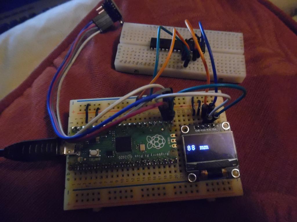 Edited 2023-09-18 07:20 by stanleyella |
||||
| NPHighview Senior Member Joined: 02/09/2020 Location: United StatesPosts: 202 |
Yes, that's the one I just got working (see above for OPTIONs). A little more difficult to connect test & analog inputs, though I have an idea... Live in the Future. It's Just Starting Now! |
||||
| phil99 Guru Joined: 11/02/2018 Location: AustraliaPosts: 2611 |
Either one of these methods:- 1) In MMEdit disable OPTION EXPLICIT and OPTION DEFAULT NONE. They are useful for large convoluted programs but for small programs they remove the flexibility of MMBasic. or 2) Add DIMs for all un declared variables to the start of the program, not at the command prompt. Dim Integer indx%, x%, samp1.addr, samp2.addr Dim Float samples!(640), samples2(320) '320 = 640-screen width |
||||
| carlschneider Senior Member Joined: 04/08/2023 Location: South AfricaPosts: 158 |
An observation, no doubt covered before, but for what it's worth, regarding the Webmite and ADC reading stability. I noticed that my ADC results were varying considerably recently, even though I was taking 20 samples and finding the mean. The input to the ADCs are fixed resistor dividers in the dev stage, so input is stable. I've also used the third ADC to find the floor noise, which I subtract from the other two ADC readings. The apparent instability in the ADC outputs was observed on the OLED display, recently installed and configured in the code dev. From comments previously read here I then hauled out my really really cheap multimeter and measured the 3.3V rails, which had drooped to 3.15V and varied about 0.01V around that. Fortunately I had a spare 100µF electrolytic cap on hand, which across the rails on the breadboard, brought the rails back up to the unloaded 3.32V originally measured; and now the ADC readings are rock steady again. Thanks to all for their comments on this thread. Cheers Carl Retirement is tough on Hobbies without a day job |
||||
| The Back Shed's forum code is written, and hosted, in Australia. | © JAQ Software 2025 |
