
|
|
Forum Index : Microcontroller and PC projects : A great PID tutorial with no talking or music.
| Author | Message | ||||
| PhenixRising Guru Joined: 07/11/2023 Location: United KingdomPosts: 1962 |
I need to build a rig like this. I come across sooo many who pretend to understand PID but who are actually clueless  |
||||
| Volhout Guru Joined: 05/03/2018 Location: NetherlandsPosts: 5942 |
Great tutorial !! All design files are included, so go ahead, and build it. 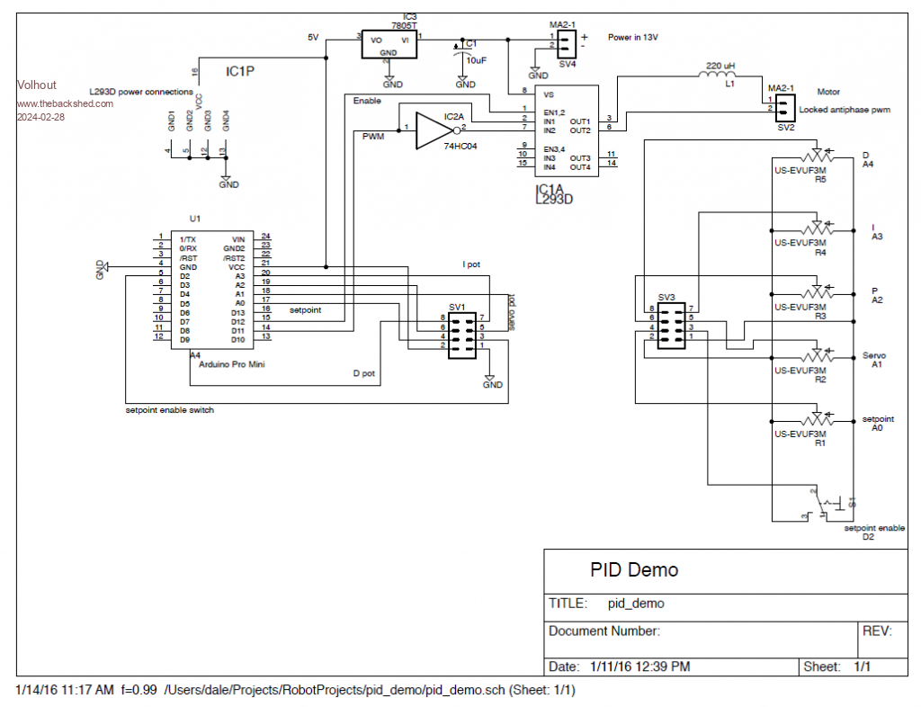 Volhout Edited 2024-02-28 18:04 by Volhout PicomiteVGA PETSCII ROBOTS |
||||
| PhenixRising Guru Joined: 07/11/2023 Location: United KingdomPosts: 1962 |
Oh, I already have something far superior, running on the ARMmite-H7 (real encoder, no pot) including acceleration feed-forward, velocity feed-forward, torque-limiting, motor-offsets, etc.No, I was referring to the mechanical rig. Much easier than trying to train people on an actual machine.  |
||||
| Turbo46 Guru Joined: 24/12/2017 Location: AustraliaPosts: 1693 |
Phenix, You have told us many times in this and in your previous incarnation, how good you are and your PID implementation is so would you mind sharing some of your code. While I believe that I understand the basic principle of PID, I struggle with the calculation of the Proportional, Integral and Derivative components of the system in MMBasic. A little help in that area would be greatly appreciated. Not asking you to give away any industrial secrets. Thinking of applying it to a heating system. Bill Keep safe. Live long and prosper. |
||||
| phil99 Guru Joined: 11/02/2018 Location: AustraliaPosts: 3294 |
The last time I dealt with this stuff it was done with the very latest IC technology - Op-Amps! For large genset governors and voltage regulators the aim was to achieve critical damping. Fastest feedback response time without causing hunting. The voltage regulator produced a 3 phase counter-rotating field for the exciter. |
||||
swoodgate Newbie Joined: 24/11/2011 Location: AustraliaPosts: 15 |
Here is a link to a series of blog posts which explain in detail the coding of a PID implementation by Brett Beauregard who produced an Arduino Library. Well worth a read. http://brettbeauregard.com/blog/2011/04/improving-the-beginners-pid-introduction/ Cheers, Steve |
||||
| Turbo46 Guru Joined: 24/12/2017 Location: AustraliaPosts: 1693 |
Thanks Fellas, I would probably have more success using op amps and I also struggle with C. It's been a long time. I may have to try to work through it. Bill Keep safe. Live long and prosper. |
||||
| PhenixRising Guru Joined: 07/11/2023 Location: United KingdomPosts: 1962 |
'Set-up a loop, as close to 1ms as possible 'Used this method because it can be modified (500us for example) timer=0 schd=0.9794 do do:loop until timer>schd:inc schd,0.9794 strt=timer 'simply for keeping an eye on loop execution time 'Read the motor's encoder (LS7366) pin(85)=0 spi write 1,&h60 spi read 4,psns() pin(85)=1 apos=(psns(1)<<24) or (psns(2)<<16) or (psns(3)<<8) or psns(4) 'apos (actual position is signed 32bit) if apos and &h80000000 then inc apos, - &hffffffff 'positionerror = command_position(setpoint)-actual_position perr=cpos-apos 'if using the integral, begin to accumulate and 'keep within the anti-wind-up limit if ki>0 then inc intg,perr if intg>ilim then intg=ilim if intg<-ilim then intg=-ilim 'standard PID 'mcmd=50 is the PWM offset for locked antiphase where '50% duty-cycle is zero motor current mcmd=50+((kp*perr)+(kd*(perr-prvr))+(ki*intg)) 'tl=torque-limit. if tl then if mcmd<tl then mcmd=tl if mcmd>tlhi then mcmd=tlhi end if 'LMD18200 datasheet advises to avoid 100% and 0% duty-cycle(whatever) if mcmd<0.2 then mcmd=0.2 if mcmd>99.8 then mcmd=99.8 'if motor-disable commanded then set duty-cycle to 50% if moff then mcmd = 50 pwm 1,18000,mcmd 'copy positionerror to previouserror for next kd calc prvr=perr fini=timer loop Obviously, a heating system would not require a 1ms loop-rate I have a lot more going on in my actual loop and still have plenty of time to read/write UARTS for command updates, etc. This loop handles both axis position and velocity. Following this is a trapezoidal or s-curve profiler with on-the-fly velocity and acceleration/deceleration change capability. Loving this ARMmite H7  |
||||
| PhenixRising Guru Joined: 07/11/2023 Location: United KingdomPosts: 1962 |
The benefit of this "discretized" method is that one simply divides a new motor position command by the loop rate and voila, we have velocity control. Command position: 3000 quadrature counts Command velocity: 3000 quadrature counts/second Each loop command increment requires 3 counts Brett Beauregard's method is "continuous" and would require something like an interrupt to schedule the command increments. Edited 2024-02-29 18:43 by PhenixRising |
||||
| PhenixRising Guru Joined: 07/11/2023 Location: United KingdomPosts: 1962 |
Feedback systems are fascinating, no matter if they're digital, analog or even mechanical. I watched a video about one of the early inventions to maintain a ship's trajectory. Governors...great example. Fascinated me, even as a kid Not enough of this is being taught, IMO. "Robotics" are supposedly being taught but using open-loop stepper-motors. Real robots utilize closed-loop servos which is the most important aspect (along with the kinematics). There's no end of demo's of articulated arms picking and placing objects but what happens when the object is clamped in something like a vise that only opens when the end-effector has gripped it. The whole arm flexes because steppers can't be made to comply. The "Torque Limit" example in my code snippet, softens-up a servo axis without losing track of motor position. The same with Cobots (collaborative robots) that are able to work alongside humans without a protective cage. They can instantly soften-up to the point where you can throw the arm around. 3d printers, stalling or losing track of where they are, due to lost pulses. If you can't verify that what you commanded, happened, you're not in control. |
||||
| Turbo46 Guru Joined: 24/12/2017 Location: AustraliaPosts: 1693 |
Thanks Phenix, That will take me some time to understand. The variable names don't mean a lot at the moment. You are right, a heating system will not need such a fast response. All I am looking for is to rise up to a particular temperature as fast as possible with very little or no hunting. I'd like to develop an approach that can be used for different applications just by tuning the parameters. It's just the algorithm I need to understand. Bill Keep safe. Live long and prosper. |
||||
| PhenixRising Guru Joined: 07/11/2023 Location: United KingdomPosts: 1962 |
I'll type a clearer version in the morning plus a couple of suggestions that would better suit a heating system. The PITA is tuning because of the slow response |
||||
| Turbo46 Guru Joined: 24/12/2017 Location: AustraliaPosts: 1693 |
Then cooling down between tests. I'll need a monitoring system with graphing capabilities. Thanks again. Bill Keep safe. Live long and prosper. |
||||
| Mixtel90 Guru Joined: 05/10/2019 Location: United KingdomPosts: 8911 |
Some heating controllers only use integral control, I think. The system is so slow and overshoot is, by and large, non-critical. One of the reasons is that most boilers are rated by the number of starts per hour that's allowed. The boiler tries to run for relatively long periods at a low firing rate and the heating valve is nudged slowly round. Sometimes it's just fed with a raw PWM signal against a return spring. Mick Zilog Inside! nascom.info for Nascom & Gemini Preliminary MMBasic docs & my PCB designs |
||||
| PhenixRising Guru Joined: 07/11/2023 Location: United KingdomPosts: 1962 |
Ah-ha, good example of why I liked the video demonstration in the OP. Many are of the opinion that they don't need a D-term. Not realising that they already have one in the form of this spring, for example. This is also true with industrial servo drives, the vast majority are configured in "velocity mode", they are rate devices. The command signal from the controller is merely a velocity reference and therefore all that's required is the P-term (velocity gain). The drive takes care of the rest. I don't care for this because the technician needs to be familiar with that particular drive calibration procedure. Out comes the laptop and the proprietary RS485 cable with the weird connector, try to remember the password and how to actually use the app "Torque mode" or "current mode" and the drive is relegated to being only responsible for providing current and commutation. That simple code that I posted above, now takes control of position, velocity and torque. Replace a bad drive and all that needs to happen is; select Torque Mode and the peak/continuous current to suit the motor. Any brand of drive can be substituted. |
||||
| PhenixRising Guru Joined: 07/11/2023 Location: United KingdomPosts: 1962 |
KISS principle: 'Simple Proportional heat control 'Objectives: ' '1) Immune to instability '2) Rapid calibration 'The premise being that hovering around a setpoint isn't 'necessary for heating.That's where we get instability. 'The important things are the fact that it's a proportional 'control and that it's consistent 'Here we have a dummy target that will never be reached because the 'loop gain won't be sufficient. Shooting for Desired+dummy but calibrated to 'output zero-heat when desired is reached. 'The command will fade away and the only 'calibration required is to tweak either the Kp or the Dummy_Target_Temp_Offset 'to have the room temperature match the desired temp. 'At Desired Temp, there will still be a differential but not enough to produce 'an output signal dim float Desired_Temp dim float Dummy_Target_Temp_Offset dim float Actual_Temp dim float Differential dim float Heat_Command dim float Kp 'Test values Kp=0.4 'stab in the dark Desired_Temp=20 Dummy_Target_Temp_Offset=4 do Actual_Temp=[sensor_reading] Differential=(Desired_Temp + Dummy_Target_Temp_Offset) - (Actual_Temp) Heat_Command=Kp*Differential [output_heat_command] pause 10000 'stab in the dark loop |
||||
| Turbo46 Guru Joined: 24/12/2017 Location: AustraliaPosts: 1693 |
Thanks Phenix, I really want to end up with a PID control even it I don't need to use all functions in the one application. Silicon Chip had a project for a reflow oven using a small cheap toaster oven using PID control some time ago and it sparked my interest. I have added Integral code using your first example as a guide. Would you mind having a look and telling me if I am on the right track? ' PID Heating control ' Well just PI for now ' D to come - hopefully ' dim float Desired_Temp dim float Dummy_Target_Temp_Offset dim float Actual_Temp dim float Differential 'Proportional dim float Heat_Command dim float Integral dim integer Looptime dim float Kp dim float Ki 'Test values Looptime=10000 ' 10 seconds for now Ki=0 'Start with zero, increase in small steps while tuning Kp=0.4 'stab in the dark Desired_Temp=20 Dummy_Target_Temp_Offset=4 ' zero if full PID? do Actual_Temp=[sensor_reading] Temperr = Desired_Temp - Actual_Temp ' INTEGRAL ' Next line Could be omitted, if Ki= 0 it then has no effect on Heat_command if ki>0 then inc Integral,Temperr if Integral>Desired_Temp then Integral=Desired_Temp 'Don't go higher than Desired Temp ' if Integral<-Desired_Temp then Integral=-Desired_Temp 'Not needed +ve only ' PROPORTIONAL Differential=(Desired_Temp + Dummy_Target_Temp_Offset) - (Actual_Temp) ' HEAT COMMAND Heat_Command=Kp*Differential + Ki*Integral ' [output_heat_command] pause Looptime loop I don't believe that PID controllers generally use the offset as part of the Proportional control - probably relying on the other components for stability. Bill Keep safe. Live long and prosper. |
||||
| phil99 Guru Joined: 11/02/2018 Location: AustraliaPosts: 3294 |
PhenixRising will probably correct me as I am quite rusty on this subject but I think the purpose of the offset here is to compensate for the average heat loss, ensuring the temp. stays a bit closer to the setpoint. In op-amp terms how much difference this makes depends on the feedback loop gain. A high gain can get it very close without an offset, at the risk of instability. Just setting the setpoint a little higher than the desired temp and "relying on the other components for stability" would probably do much the same thing. Eg if you want 20° set 20.5°. Edit If chasing the very highest precision the offset could vary with the difference between the indoor and outdoor temps. When the outdoor temp falls it would anticipate that the indoor temp is going to fall and be cranking up the heating in advance. This is similar to the genset governors that used "load anticipation". A sudden change in load would briefly change the setpoint offset to increase / decrease fuel injector timing before the frequency actually changed, "heading it off at the pass". Edited 2024-03-02 22:17 by phil99 |
||||
| The Back Shed's forum code is written, and hosted, in Australia. | © JAQ Software 2026 |
