
|
|
Forum Index : Microcontroller and PC projects : JLC PCB
| Author | Message | ||||
| PEnthymeme Regular Member Joined: 27/12/2023 Location: United KingdomPosts: 42 |
Happy Sunday Further to my "discharging a battery" thread, I designed a simple PCB with three different selectable resistive loads. First time ever designing a PCB and first time getting one made. 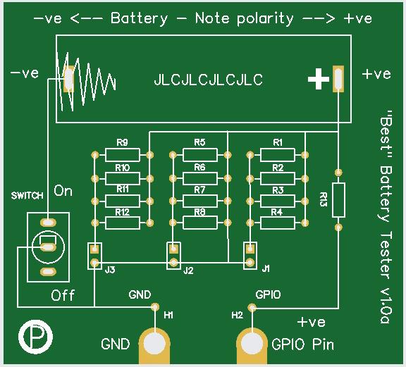 The PCBs cost £5 for 10 (seems to be the going rate) and delivery was £13. The real eye opener was the delivery: Reverse order: PONTYCLUN, UK RIDGMONT, UK STANSTED,UK ROISSY CHARLES DE GAULLE CEDEX, FR DUBAI WORLD CENTRAL NEW DELHI, IN GUANGZHOU, CN Roughly 14,000km in 3 days for £13. No wonder the postal service (UK) is on its knees. Anyway, three boards made and tested -- works a treat. The board works fine and should meet the needs of the hands-on session. Oddly satisfying to design and get these made. Px |
||||
| lizby Guru Joined: 17/05/2016 Location: United StatesPosts: 3785 |
Nice. Can you provide more information? Gerbers or design files? Are these 18650 batteries? Could you put values for the resistors on the PCB (silkscreen)? EasyEDA? How do you use it? In what circumstances do you use the jumpers? PicoMite, Armmite F4, SensorKits, MMBasic Hardware, Games, etc. on FOTS |
||||
| PEnthymeme Regular Member Joined: 27/12/2023 Location: United KingdomPosts: 42 |
Doh! Sorry. It is sized for AA. The resistor banks are 3 banks of 4 - in parallel. The jumpers are to switch in combinations of the banks. The values are: Bank 1 - 4 x 100ohm (giving 25 ohm in parallel - load shared over x4 resistors) Bank 2 - 4 x 47ohm ( giving 11.75ohm in parallel load shared over x4 resistors) Bank 3 - 4 x 22ohm (giving 5/5ohm in parallel load shared over x4 resistors) By jumpering the parallel circuits you can either use each bank as is or combine them in parallel -- so Bank 1(25 ohm) and bank 2(47ohm) gives overall 8ohms (load now shared over 8 resistors). The idea is that students can test AA cells under different loads as needed - mostly to see if it makes a difference. Not adding the resistor values to the PCB was a conscious choice as they will be soldered as part of the maker-fare and students can choose their own resistors. That said, having assembled x3 - the resistors go in fine, so does the battery holder and switch -- but the single post headers are fiddley -- if a revision x2 happens, I will change to a block of headers. The exposed connectors at the edge are to use the Microbit with croc clips. The Headers just above replicate those. I have written code in MakeCode (Microbit) and MMBasic (Pico) and it is relatively simple. The "sell" of the Pico version is the ability to save the data to file and not just serial display (Microbit v2 does allow access to its filesystem so it does work in a similar manner to the Pico with MMBasic -- but most schools still have v1.) I will share the gerbers etc when I get back to the computer with them on. Open to any tweaks to make this more useful. Px |
||||
| The Back Shed's forum code is written, and hosted, in Australia. | © JAQ Software 2026 |
