
|
|
Forum Index : Microcontroller and PC projects : MAX335 8 Channel Analog Switch
| Author | Message | ||||
| asknik2022 Regular Member Joined: 26/03/2022 Location: United KingdomPosts: 94 |
I have been using a Maxim MAX335 8 Channel Analog Switch which is controlled by SPI I have been searching for a 4 channnel version and wondered if any one on this forum could help. |
||||
| oh3gdo Regular Member Joined: 18/11/2021 Location: FinlandPosts: 47 |
https://www.tme.eu/gb/katalog/?params=383:1443902_number-of-channels:4&onlyInStock=1&queryPhrase=analog%20multiplexer Here is 4 channel analog multiplexers Pekka |
||||
| Volhout Guru Joined: 05/03/2018 Location: NetherlandsPosts: 5072 |
ADGS1212 or ADGS1412 = 4 STSP ADGS1209 or ADGS1409 = 2x 4:1 mux Volhout Edited 2024-05-21 21:16 by Volhout PicomiteVGA PETSCII ROBOTS |
||||
| asknik2022 Regular Member Joined: 26/03/2022 Location: United KingdomPosts: 94 |
I was hoping that there was a Through hole version. An alternative, can someone suuggest an alternative way to do the folowing without using transistors. I am using the MAX335 in conjuntion with an ULN2803A to independantly control 4 12V relays in order to switch between various Audio inputs (eg, Phono,Tape,cd etc) via the SPI interface on a Pico I don't want to waste 4 pico pins as I am also controlling LCD and PGA2310 Audio chip via SPI and want to keep as many pins availbale for future expansion etc. |
||||
| Andy-g0poy Regular Member Joined: 07/03/2023 Location: United KingdomPosts: 75 |
Add a spi based io expander and use that to address the switch. You can then consider things such as the CD4051/2/3 and the 74HC4051/2/3 Andy |
||||
| Mixtel90 Guru Joined: 05/10/2019 Location: United KingdomPosts: 7889 |
Personally I'm old fashioned and would attempt to remove all computer noise from anywhere near audio signals, even if that means using four IO pins, four transistors and four gold flashed contact relays. Layout is everything, keep audio leads short and run long, clean DC signals to the relay coils rather than SPI to a chip. It takes up more PCB but IMHO that's minor inconvenience. If one signal is the default the relays can be a tree (one spdt, one dpdt), so you only need two pins to select 00. 01, 10 or 11. It's a good idea to think about output muting during any input switching too, no matter how you do it. Mick Zilog Inside! nascom.info for Nascom & Gemini Preliminary MMBasic docs & my PCB designs |
||||
| asknik2022 Regular Member Joined: 26/03/2022 Location: United KingdomPosts: 94 |
Audio Relay board.pdf This is the circuit diagram of my relay board using the MAX335 and it works very well and I dont hear any computer noise at all. However since I am really only using 4 channels and it is getting harder to find (at a reasonable cost) the MAX335 chips in Through Hole that I am looking for an alternative The inputs 5 and 6 are also programmable via the MAX335 as an input or output mode (eg record out) |
||||
| Mixtel90 Guru Joined: 05/10/2019 Location: United KingdomPosts: 7889 |
It's getting more difficult to get through-hole anything now, especially ICs. :( Mick Zilog Inside! nascom.info for Nascom & Gemini Preliminary MMBasic docs & my PCB designs |
||||
| Volhout Guru Joined: 05/03/2018 Location: NetherlandsPosts: 5072 |
Andy, Typically you can connect a 74HC595 to a SPI bus (even in combination with other SPI peripherals) and use the 8 outputs to drive the ULN2803. And these are in DIL-16. 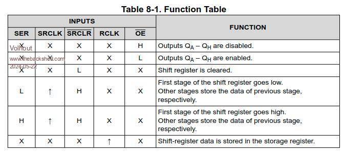 OE = low SER = SPI data in SER_CLK = SPI clock SRCLR = high RCLK = latch pulse low-high-low to transfer data to output pins Volhout PicomiteVGA PETSCII ROBOTS |
||||
| phil99 Guru Joined: 11/02/2018 Location: AustraliaPosts: 2626 |
The 74HC595 can be driven with just 1 Pico pin by using Bitstream to combine the signals. A handful of other components separate the various signals for the 74HC595. 74HC595 with 1 pin control The post has a few edits with the final circuit toward the end. The last TBS upgrade has mangled some of the example code. If anyone is interested I can re-post it. |
||||
| Volhout Guru Joined: 05/03/2018 Location: NetherlandsPosts: 5072 |
Hi Phil, I missed this when you published it. Nice... But there is already a SPI bus on the board. So using a 595 as SPI device look simple (you can even use the chip select (active low) to latch the data, since the RCLK (latch) line is edge sensitive... So wire it like the MAX335, and send only 8 bits... Volhout PicomiteVGA PETSCII ROBOTS |
||||
| asknik2022 Regular Member Joined: 26/03/2022 Location: United KingdomPosts: 94 |
Thank You Volhout This is very interesting and I will experiment etc. |
||||
| The Back Shed's forum code is written, and hosted, in Australia. | © JAQ Software 2025 |
