
|
|
Forum Index : Microcontroller and PC projects : My 44-pin Pico 2 - pics
| Author | Message | ||||
| Mixtel90 Guru Joined: 05/10/2019 Location: United KingdomPosts: 8911 |
This brings out extra signals: GP25-TP5 TP2-DM (D-) GP23-TP4 TP3-DP (D+) Pin1 Pin40 Pin2 Pin39 etc. As you can see, it is still 0.1" breadboard compatible and the extra pins are easily removed later if you decide that you don't want them. You could do this with any of the RP Pico modules but the signals may not be available on some clones. GP23 is only available if you are using an external 3V3 regulator. It has an on-board 100K pull down resistor. 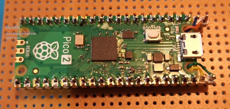 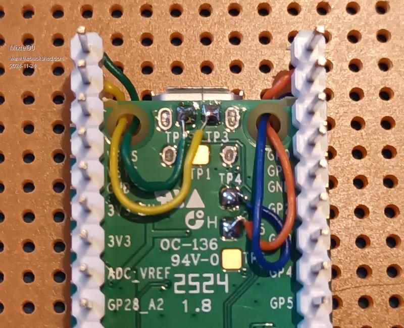 Mick Zilog Inside! nascom.info for Nascom & Gemini Preliminary MMBasic docs & my PCB designs |
||||
| stanleyella Guru Joined: 25/06/2022 Location: United KingdomPosts: 2807 |
are they the ones that use the ground pins as extra pins? I seen them. sorry,they not :( Edited 2024-11-25 05:04 by stanleyella |
||||
| Mixtel90 Guru Joined: 05/10/2019 Location: United KingdomPosts: 8911 |
No. This is a normal, official Pico 2. The one with the RP2350A on it. I just added 2 extra pins on each side to get extra signals onto the board. Mick Zilog Inside! nascom.info for Nascom & Gemini Preliminary MMBasic docs & my PCB designs |
||||
| IanT Senior Member Joined: 29/11/2016 Location: United KingdomPosts: 130 |
A simple but useful idea Mick - Thank you! :-) IanT |
||||
| The Back Shed's forum code is written, and hosted, in Australia. | © JAQ Software 2026 |
