
|
|
Forum Index : Microcontroller and PC projects : Dedicated to PicoMite ..a draft
| Author | Message | ||||
| dddns Guru Joined: 20/09/2024 Location: GermanyPosts: 848 |
Hello everybody :) I have realized a long-term thought and built an autonomous computer-based electronic development console. It is just a draft an still work in progress. Electronic wise it is running already very well at 378Mhz. Working with the console and the editor on this 7" display is just very nice and scrolling in every direction is at least as fast as on a 115200 terminal session. The display is removable and can be inserted in portrait as well as used stand-alone. It will have speakers and an amp integrated. The battery holds the power for about 3,5 hours with system load. It can be charged while using it, has a bms and does load balancing. The power monitor is done with a INA3221 and a critical current alert threshold can be set. This can be adjusted through the rotary on all 3 channels. On alert a trigger pin will go low and triggers a schmitt-trigger which cuts off the ground through a mosfet. This takes place autonomously at around 10Khz and protects pretty well. Everything is built at home with only open source software. It only consists of china modules or conventional parts in THT/2,54mm technique. The pcbs are milled. Cheers Dietmar 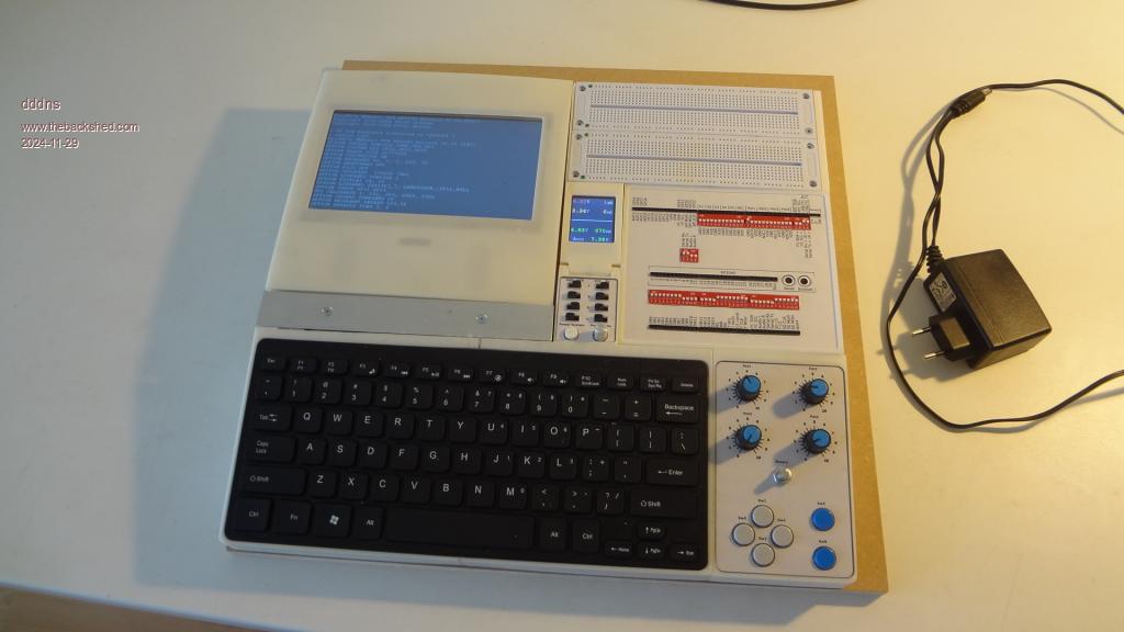 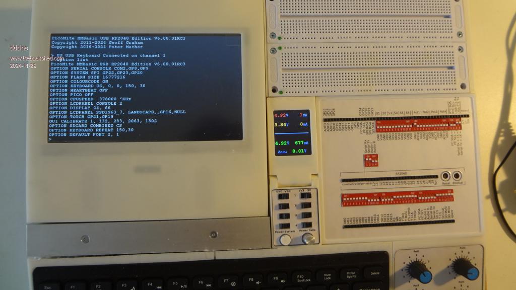 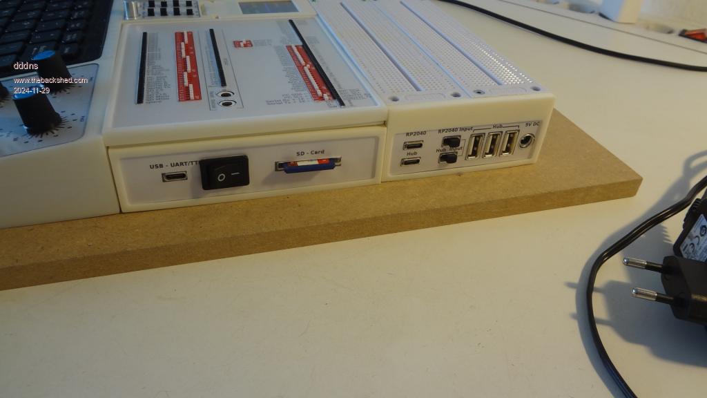 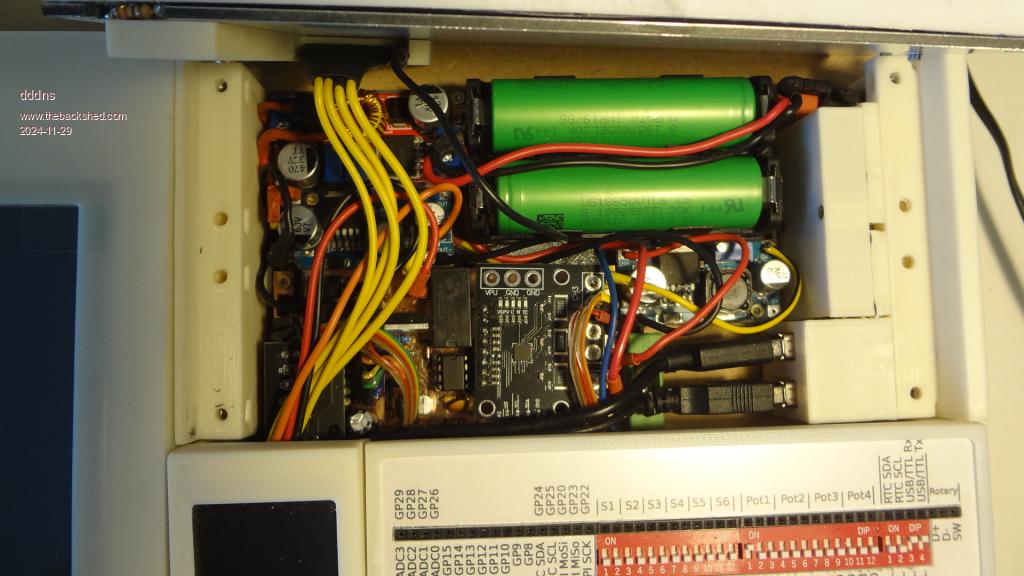 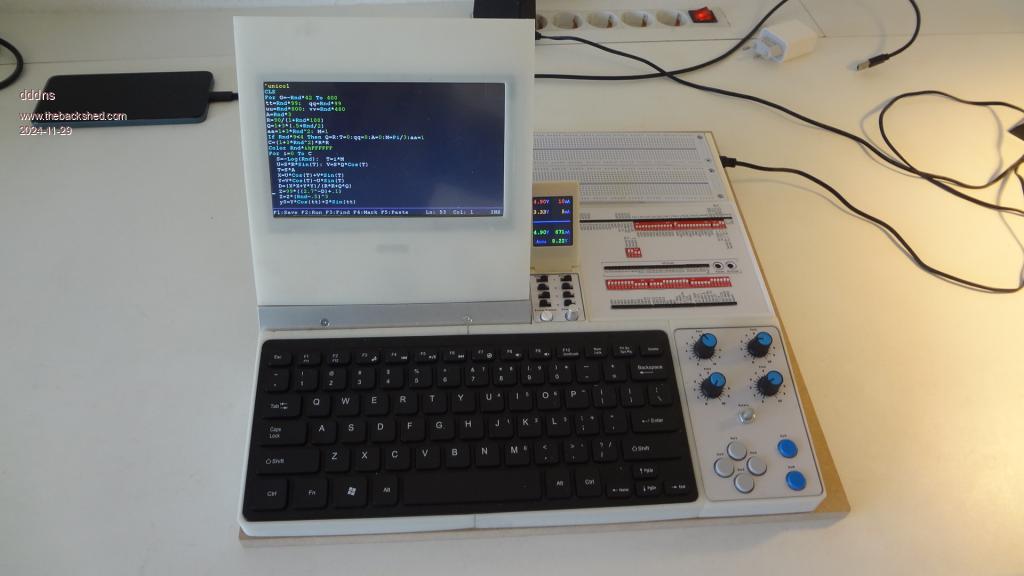 |
||||
| WhiteWizzard Guru Joined: 05/04/2013 Location: United KingdomPosts: 2991 |
Nice work. Is the 7" just for the console? I ask, because there is also a smaller TFT next to it also being driven with something. So, maybe two Picos in there - one for each display? OR is the smaller display just for battery monitoring? Just curious...... Edited 2024-11-29 21:19 by WhiteWizzard |
||||
| Volhout Guru Joined: 05/03/2018 Location: NetherlandsPosts: 5936 |
Hi dddns, Nice edutation tool. Could be something for schools. Volhout PicomiteVGA PETSCII ROBOTS |
||||
| dddns Guru Joined: 20/09/2024 Location: GermanyPosts: 848 |
The small display is exclusively a power monitor. The power on the rails of the breadboard can be switched on/off and can be configured to supply 5V or 3.3V or ground. Then you can see the consumption of the whole system and the consumption on the power rails of the breadboards. |
||||
| dddns Guru Joined: 20/09/2024 Location: GermanyPosts: 848 |
Thanks ..that would be a dream |
||||
| lizby Guru Joined: 17/05/2016 Location: United StatesPosts: 3784 |
Very nice. Complex and tidy at the same time. Which 18650 battery modules are you using? PicoMite, Armmite F4, SensorKits, MMBasic Hardware, Games, etc. on FOTS |
||||
| andreas Senior Member Joined: 07/12/2020 Location: GermanyPosts: 226 |
wow!  -andreas |
||||
| dddns Guru Joined: 20/09/2024 Location: GermanyPosts: 848 |
Thank you. They sold them as Sony VTC6 3Ah. |
||||
| lizby Guru Joined: 17/05/2016 Location: United StatesPosts: 3784 |
Thanks but I meant not the batteries themselves, but what you have them inserted into--and if it's not all one piece, the red module to the left of the batteries. PicoMite, Armmite F4, SensorKits, MMBasic Hardware, Games, etc. on FOTS |
||||
| Mixtel90 Guru Joined: 05/10/2019 Location: United KingdomPosts: 8911 |
Looks like a normal 2-cell 18650 holder to me. The charger is the blue PCB just below it at the RHS, I think. I once used a similar holder in a little power supply. Mick Zilog Inside! nascom.info for Nascom & Gemini Preliminary MMBasic docs & my PCB designs |
||||
| dddns Guru Joined: 20/09/2024 Location: GermanyPosts: 848 |
The upper left modul is a constant current stepdown converter. It is setup to 8.4V and 2.5A This delivers the power through a diode to the bms which charges till 8.4V at the batteries is reached. The power switch cuts both poles between bms and a 30W stepdown converter which generates 5V (below the red). From this It goes to another stepdown to the right which generates the 3.3V. All that power coming from the main switch goes through the INA3221 which measures total, 5V and 3.3V on its three channels. So if the main switch is off, the only power consumption comes from the bms which is 10µA. 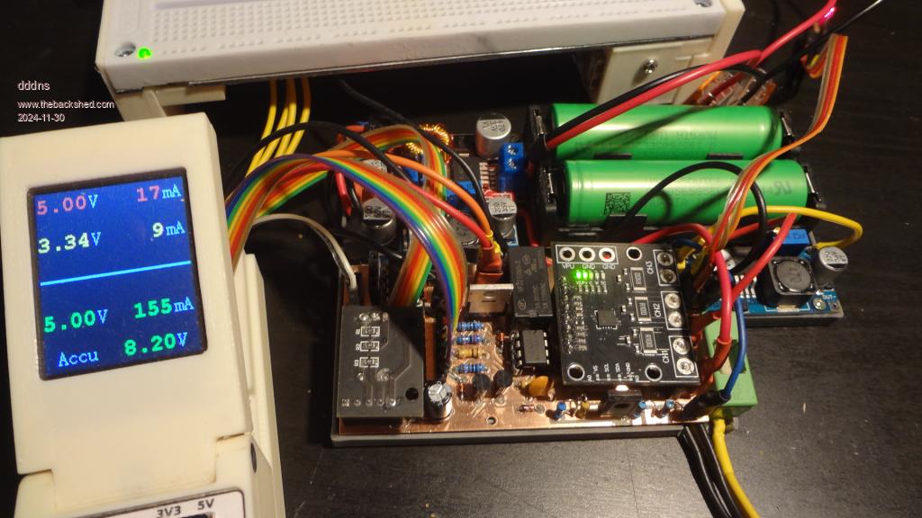 |
||||
| Mixtel90 Guru Joined: 05/10/2019 Location: United KingdomPosts: 8911 |
Very nice indeed. :) Mick Zilog Inside! nascom.info for Nascom & Gemini Preliminary MMBasic docs & my PCB designs |
||||
| stanleyella Guru Joined: 25/06/2022 Location: United KingdomPosts: 2807 |
interesting project. I got pico 2 hdmi usb but it's still breadboard, car reversing hdmi monitor and usb kb but usb to ttl . got to vero when I sorted sound filter. make something similar for my grand son. he's 8 but does html, try him with basic maybe :)  |
||||
| PeteCotton Guru Joined: 13/08/2020 Location: CanadaPosts: 631 |
Absolutely brilliant! Nice work! |
||||
| The Back Shed's forum code is written, and hosted, in Australia. | © JAQ Software 2026 |
