
|
|
Forum Index : Microcontroller and PC projects : Cheap efficient adjustable linear power supply
| Author | Message | ||||
| Volhout Guru Joined: 05/03/2018 Location: NetherlandsPosts: 5936 |
This post is just an idea that I want to share to the forum. When time permits it will grow to a picomite based adjustable power supply. But the basis is shared here in this post. Lab Bench Power Supply Lab Bench power supplies are in 2 categories, 1/ Linear power supplies ( mostly famous because of their low ripple and noise) but typically have a bad efficiency (heatsinks that get warm). A typical application is the LM317 linear regulator for a small 1A 30V supply. Similar to this: 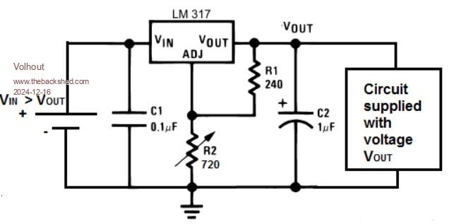 2/ Switchmode power supplies ( famous for their good efficiency ( but poor noise behaviour). For similar powers you can use the cheap LM2596 boards as depicted below. 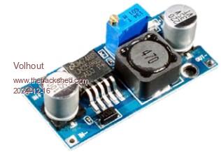 The schematics are found on the internet, and are these: 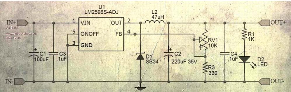 The combination of a pre-regulator and a post regulator. Very good results can be achieved when the linear regulator is given the optimal input voltage to perform it's task, something like 3V dropping on the LM317. That can be achieved by combining the switching pre-regulator and the linear post regulator as below. Remove the potmeter from the LM2596 board. 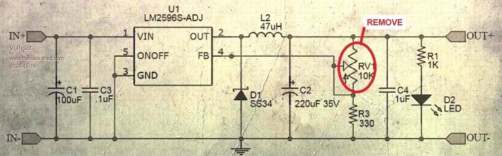 The adjustment of the switching regulator is replaced by a circuit that makes it track the output voltage for the linear regulator. The 680 ohm resistor deternings the LM317 drop voltage. 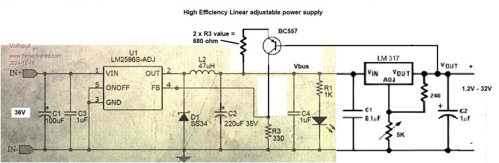 I purchased the LM2596 board for 1 euro, and the LM317 for 50 cents. The whole power supply is below 2 dollar (except for the 36V source). This idea works fine, the LM317 needs only a very small heatsink, for a continuous 1A output. For real low noise, an LC filter between LM2596 and LM317 is needed. This is not a complete bench power supply, but the idea forms the basic for the power supply in development. It is just that somebody might find this beneficial. Volhout Edited 2024-12-16 23:50 by Volhout PicomiteVGA PETSCII ROBOTS |
||||
| robert.rozee Guru Joined: 31/12/2012 Location: New ZealandPosts: 2529 |
see also: https://sound-au.com/articles/preregulators.htm#s5 cheers, rob :-) |
||||
| Mixtel90 Guru Joined: 05/10/2019 Location: United KingdomPosts: 8911 |
I have a circuit somewhere that was in an old magazine. It has a low frequency prereg that charges the reservoir capacitor via a MOSFET then cuts off the charge partway up the cycle (controlled by a thyristor). That maintains the voltage on the cap at a controlled level. A transistor measures the voltage across the linear regulator that follows it. I find it very interesting as there is no HF generation at all. Obviously, it's bulky as it uses a conventional mains transformer. Apparently the transformer can be a bit "buzzy" due to the unusual load on it, only charging the reservoir in pulses. I'll see if I can find it. Mick Zilog Inside! nascom.info for Nascom & Gemini Preliminary MMBasic docs & my PCB designs |
||||
| Volhout Guru Joined: 05/03/2018 Location: NetherlandsPosts: 5936 |
Robert, Some of thesecircuits look the same but operate different. The circuit proposed above is a linear feedback system that does not need any tuning since it relies on the feedback gain and phase that was originally designed. The circuits in your article increase the gain, and therefore require careful tuning to maintain stability. Volhout Edited 2024-12-17 04:09 by Volhout PicomiteVGA PETSCII ROBOTS |
||||
| Mixtel90 Guru Joined: 05/10/2019 Location: United KingdomPosts: 8911 |
This isn't the original, but it's more or less the same circuit. Blackdog didn't originate it either, it's far older. IIRC it was in Practical WIreless. Try this - it explains it There's a link to EEblog on there, which shows the original circuit from the magazine. There is also quite a bit more info from Blackdog, including a Spice model. . Edited 2024-12-17 05:44 by Mixtel90 Mick Zilog Inside! nascom.info for Nascom & Gemini Preliminary MMBasic docs & my PCB designs |
||||
| phil99 Guru Joined: 11/02/2018 Location: AustraliaPosts: 3293 |
Toshiba used something similar in their VCRs. As the thyristor controlled the transformer primary in their version standby power averaged about 50mW when most of the others at that time were around 1 or 2W. |
||||
| Mixtel90 Guru Joined: 05/10/2019 Location: United KingdomPosts: 8911 |
It's a design that I intended trying at one point but never got round to it. Others seem to have had it working pretty well, sometimes with a little tuning of the bc capacitor on the transistor to make it work optimally with some transformers. Mick Zilog Inside! nascom.info for Nascom & Gemini Preliminary MMBasic docs & my PCB designs |
||||
| Volhout Guru Joined: 05/03/2018 Location: NetherlandsPosts: 5936 |
Mick, Pre-conditioning with SCR's cannot be used anymore due to the terrible power factor. Anyway, you have given me lots to think about. Thank you. Volhout PicomiteVGA PETSCII ROBOTS |
||||
| Mixtel90 Guru Joined: 05/10/2019 Location: United KingdomPosts: 8911 |
If the PF on that is bad, try a capacitive dropper - and they are in almost all domestic LED lights, with no PF correction. :) It would be interesting to see the PF on that design as it's still a standard FW rectifier, it's just that not all of the cycle is used. In fact, it's just like a trailing edge dimmer used for LED lighting. I don't think they have terrible PF problems. Mick Zilog Inside! nascom.info for Nascom & Gemini Preliminary MMBasic docs & my PCB designs |
||||
| astroboy Regular Member Joined: 28/12/2014 Location: AustraliaPosts: 41 |
I'm really interested in this idea and hope it might eventually become a project. I hope it hasn't been forgotten about. Regards John |
||||
| aFox Senior Member Joined: 28/02/2023 Location: GermanyPosts: 110 |
Hi Vollout That would be a project for me. How would you design the LC filter? Merry Christmas to all Gregor Edited 2024-12-26 06:46 by aFox |
||||
| Volhout Guru Joined: 05/03/2018 Location: NetherlandsPosts: 5936 |
Hi aFox, A linear regulator like an LM317 has a pretty good ripple rejection for 50 and 100Hz (anything below 1kHz), but is not very good for 180kHz (the switching frequency of the LM2596) and above. That is why you need a LC filter. I succesfully tried a 47uH inductor and 100uF capacitor without calculation. The inductor should be rated 1A minimum. With a 180kHz ripple of 1Vpp, you need 60dB (a factor 1000) rejection to get to 1mVpp. 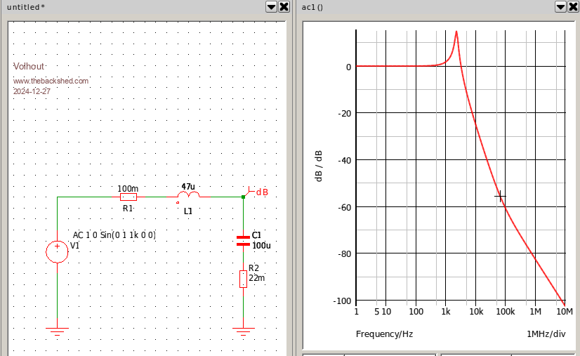 The resistors are part of inductor/capacitor according the datasheet. The disadvantage of the LM317 is that for current limit and short circuit protection, you would need a negative voltage. Do able, but complicating. So the LM317 - needs a negative voltage when adjustable current limit is required. - cannot be used as reference, since you want if controlled from a DAC (the DAC Vref will be the reference) or PWM (pico voltage is the reference).. - has poor ripple rejection for 180kHz. So apart form the nice TO220 package it has no benefits. This does not make LM317 an ideal candidate. Although I have a circuit drawn and prototyped, I am drifiting off into a new design that simply uses a medium power transistor in combination with an LM358 opamp and the above 2596 switcher board. Volhout Edited 2024-12-27 07:13 by Volhout PicomiteVGA PETSCII ROBOTS |
||||
| Mixtel90 Guru Joined: 05/10/2019 Location: United KingdomPosts: 8911 |
I've come up against this with LM317 designs. It's not a good chip for a general purpose lab supply. You need a negative rail for 0v output and current limit has to be sensed in some other way to be of any use. The method of varying the voltage is only optimal over a restricted range. Toward the edges of that range regulation suffers. The package is power limited, which will usually protect against overloads, but no guarantee into a short circuit. Of course, it was never designed for this. It's designed to be a programmable fixed voltage regulator and it's good at that. By the time you've messed about making an unsatisfactory supply out of two or more LM317s you may as well have used a twin op amp, a transistor or so and a power transistor for the output. It'll probably be less complicated and work better. :) Mick Zilog Inside! nascom.info for Nascom & Gemini Preliminary MMBasic docs & my PCB designs |
||||
| Bleep Guru Joined: 09/01/2022 Location: United KingdomPosts: 809 |
Hi Harm, I know your original title is 'linear' but here is my take on a cheap-n-chearfull bench PSU partially from the junk box. Dual 0-32v at up to 5.1A, with digital displays & current and voltage limits. 2 x 19V 130W laptop bricks. 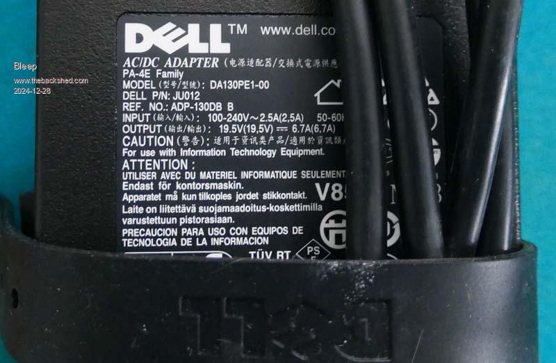 2 x DP30V5A Digital-controlled 160W 32V 5A Buck PSU constant volt/current 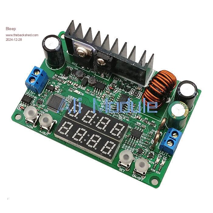 2 x 150W DC-DC Boost Converter Step Up Power Supply Module 10-32V To 12-35V 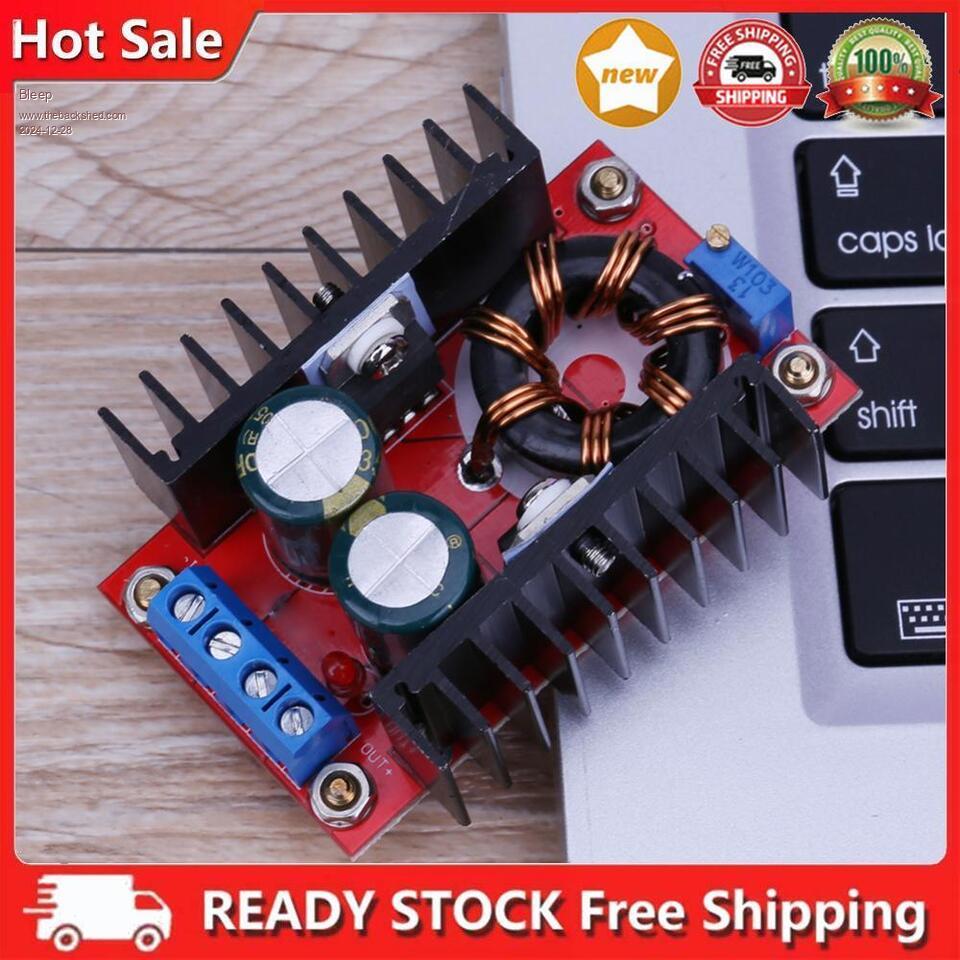 Sundry, switches, terminal posts and one NTC. Makes one of these:- 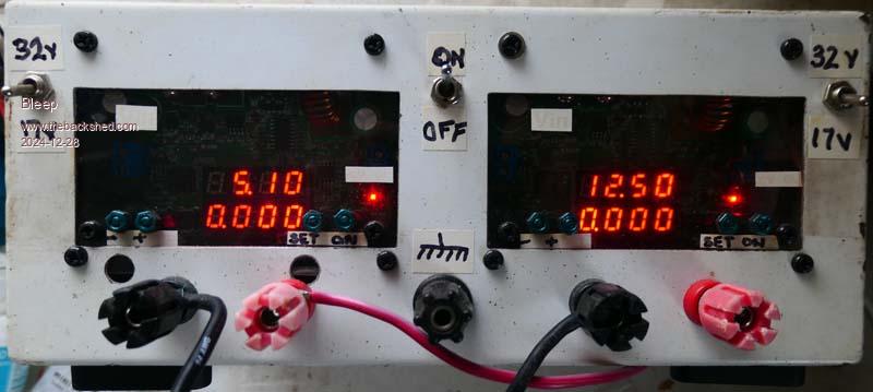 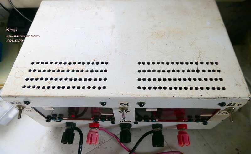 Each brick, poweres it's own Digital voltage/current controller, which would only normally give 18V output, so there is also 2x 150W step up converters to give the 34V required to give the full 0-32V range, these can be switched in and out as required. I wanted to be able to charge Lead Acid batteries occasionally, which this is easily capable of, 10.2A at 14V, both channels paralleled up. The current limit is very usefull, especially when prototyping new builds, or for re-charging batteries, especially Lithium. I found the NTC on the mains input to the bricks was required, only after I had destroyed 2 mains power toggle switches. :-( You presumably could make it quieter by adding your LC filter. :-) Regards, Kevin. Edited 2024-12-28 23:22 by Bleep |
||||
| Mixtel90 Guru Joined: 05/10/2019 Location: United KingdomPosts: 8911 |
Switching supplies have their uses, and can be really useful where high current is needed. You run into problems as soon as you introduce high speed switching anywhere in the chain if the output is to be low level and low noise though. Those switching frequencies often have to be completely filtered out for analogue circuits, and can cause beat frequencies in RF circuits. Unfortunately analogue supplies are often bulky and hot if you want any sort of current. They are also often temperamental. Power supplies, like amplifiers, make great oscillators! There is a lot of work in getting a good, stable analogue supply. Unfortunately there's no substitute for one apart from batteries, and even those aren't always as good. This is interesting: https://www.paulvdiyblogs.net/2017/07/my-new-power-supply.html Edited 2024-12-28 23:49 by Mixtel90 Mick Zilog Inside! nascom.info for Nascom & Gemini Preliminary MMBasic docs & my PCB designs |
||||
| The Back Shed's forum code is written, and hosted, in Australia. | © JAQ Software 2026 |
